Joining Processes #
Welding-based #
There are many ways of assembling mechanical components to create mechanisms and structures. Examples of joining processes include the use of fasteners such as bolts and rivets, adhesives, and push fits, in which interference is used to connect components together. Welding, meanwhile, involves fusing two components by melting the material near their interface, and possibly introducing additional material of the same kind to fill any gaps between the components. Metallic and polymeric materials can be welded, and the techniques used to melt the material vary with the properties of the materials being joined.
It is important to note that welding involves complete fusion of the components being joined: the joint is made of the same material as the components and thus can be extremely strong relative to other joining techniques because it enables us to eliminate inter-material interfaces along which cracks might propagate. Drawbacks of welding, however, include the fact that because we are heating a portion of the components above their melting point, dimensional distortion of the components may occur, and even if distortion does not occur there may be modification of the material’s mechanical properties in a heat affected zone (HAZ) around the weld. This property modification may involve recrystallization or annealing of metallic materials, softening the component after it cools.
Welding terminology #
A heat source emits heat some distance from the weld. A fraction .$f_1$ of this heat reaches the material, and a fraction .$f_2$ of the heat that arrives is retained within the weld region, and actually is used in melting material. The remainder of the heat is lost either to the surroundings, or conducted through the solid components where it may modi.$f_y$ the microstructure without melting the material. The energy required for melting a unit volume of the material may be approximated as being proportional to the square of the absolute melting temperature. If we know the rate of heat generation and the heat transfer factor .$f_1$ and melting factor .$f_2$, we can thus determine the volumetric rate at which material can be melted and thus how fast a weld with a given cross-sectional area can be created
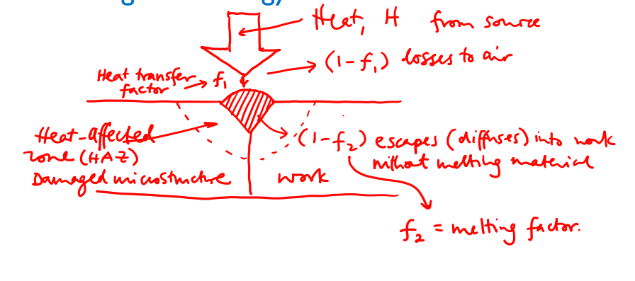
- Proportion of total heat from source contributing to melting of metal: .$f_1 f_2 H$
- .$H$: Heat from source
- .$f_1$: Heat transfer factor – amount of heat that goes into welding material
- .$f_2$: Melting factor – amount of heat that goes into welding region
- Energy required for melting:
$$U_m = K T^2_m$$
- .$U_m$: Melting energy (J/mm.$^3$)
- .$K = 3.33 \cdot 10^{-6}$ J/(mm.$^3$K.$^2$)
- .$T_m$: Melting temp (K)
- Power for melting:
$$U_m A_w v = f_1 f_2 IE$$
- .$IE$: Electric Power
- .$I$: Current (Amps)
- .$E$: Voltage (Volts)
- Rates of melting material:
$$R_{H,w} = f_1 f_2 R_H = U_m R_{w, V} = U_m A_w v$$
- .$R_{H,w}$: Rate of heat delivery to weld [.$W$atts]
- .$R_H$: Power of heat source
- .$R_{w,V}$: Volumetric rate of melting; .$A_w v$
- .$U_m$: Melting energy (J/mm.$^3$)
- .$A_w$: Cross-section area of weld
- .$v$: Velocity of heat source
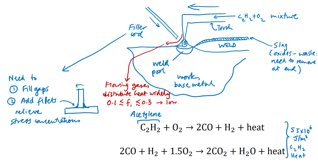
Oxyacetylene welding #
This versatile technique has been used for many decades to weld metals, and involves a two-stage reaction, first the combustion of acetylene to produce carbon monoxide, hydrogen and heat, and second the reaction of the CO with hydrogen and oxygen to produce carbon dioxide, water, and more heat.
This approach lends itself to welding in remote locations (all that is needed is a gas tank and torch) and because of the high temperature of the flame, many materials can be welded. Can also be done underwater.
One well known challenge with this technique is hydrogen embrittlement where the hydrogen gas generated can become incorporated into the microstructure of the component, weakening it.
@ 1:00
Arc welding #
In arc welding of any kind, a voltage is applied between the workpiece and an electrode which are separated by a gap of a few millimeters. The electric field across this gap is large enough to ionize the gas and generate a plasma in the gap. This plasma is electrically conductive, yet still highly resistive so that heat is generated as the current passes through the plasma. It is this heat that melts the material. Because the plasma is so highly localized and the heat is generated within a millimeter or so of the weld, the welded region can be precisely controlled.
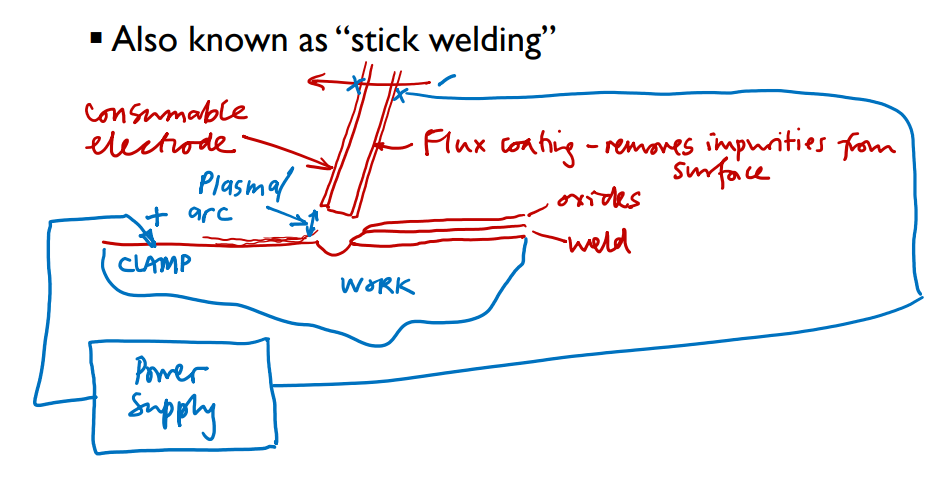
Manual Metal Arc (Stick) Welding #
In Manual arc welding, the electrode is a hand-held rod of the same material as the workpiece, and it melts as the weld forms, providing material to fill the gap between components. The rod has a length of several inches, so the length of weld that can be produced in one welding operation is limited. This limits the speed of the technique. The rod is usually coated with a flux, which melts during welding to produce an acidic liquid on the surface of the work, etching away naturally occurring oxides to expose the metal surface and enable a strong, continuous metallic weld to be produced.
@ 1:37
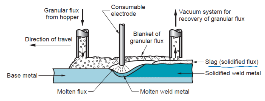
Submerged arc welding #
This process is suitable for producing long, straight welds in larger components. The electrode is a consumable wire that is fed into the system from a spool, and a powdered flux is fed in front of the advancing weld from a hopper. The weld region lies submerged by the flux, which helps to prevent sparks and strong ultraviolet radiation from the weld escaping from to the surroundings. The flux and electrode handling mechanism is usually mounted on a motorized carriage that moves along the component at a constant rate.
@ 3:06
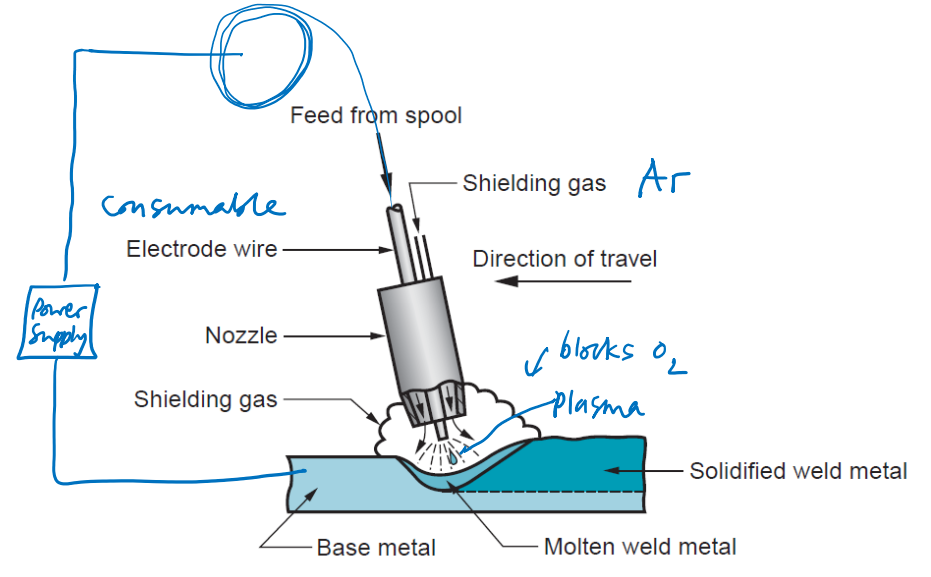
Metal Inert Gas (MIG) Welding #
Here, the electrode is consumable and fed from a continuous spool of wire. Instead of flux, an inert gas such as Argon is fed around the electrode as a shield, to prevent oxidation of the workpiece surface.
@ 5:50
Dip vs Spray Transfer in MIG Welding #
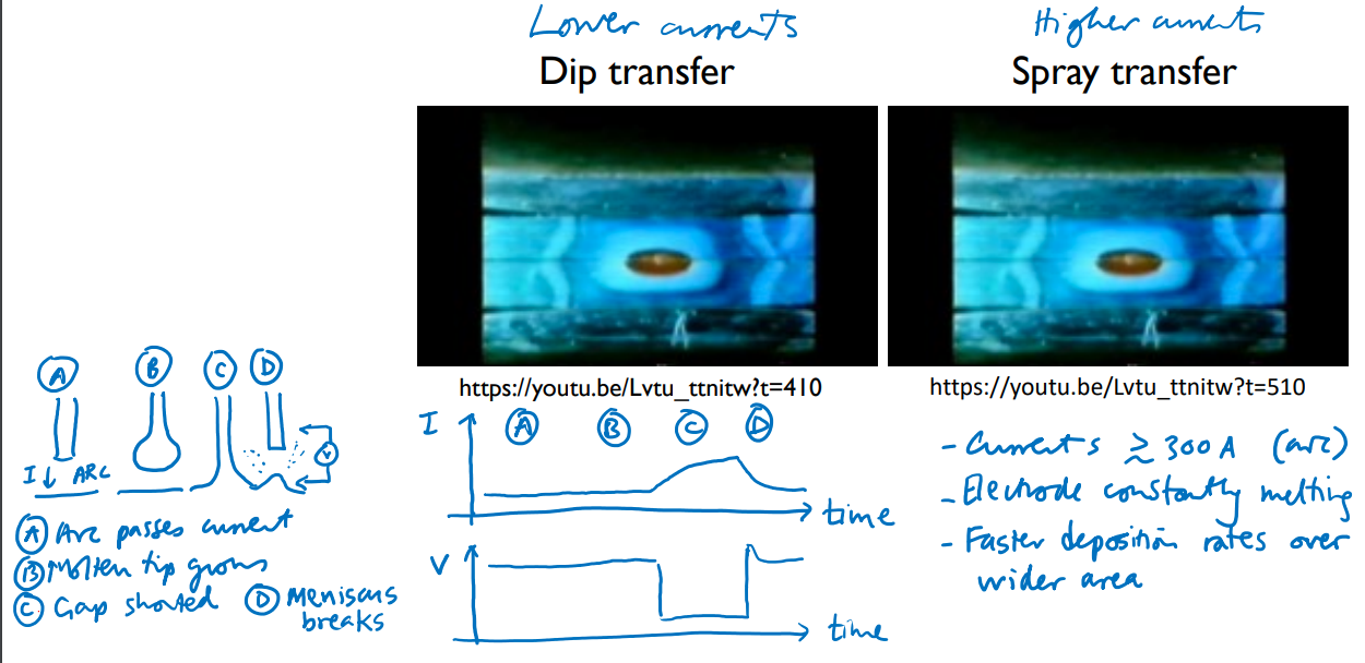
@ 6:50 + 8:30
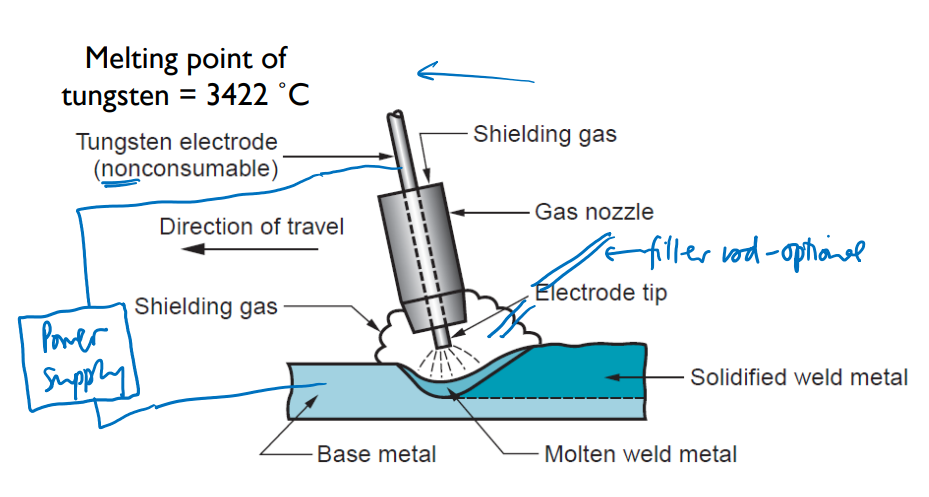
Tungsten Inert Gas (TIG) Welding #
Like MIG welding, an inert gas shield is used, but instead of a consumable electrode, a tungsten electrode with much higher melting point is used. If filler material is needed it is introduced from the side using rods of materials. The electrode can maintain a sharp shape (less than a millimeter diameter), so that highly precise and consistent welds can be produced. This also makes it much harder to learn.
@ 11:25
- DC (Direct Current)
- Electrode is held negative
- Suitable for all metals except Al and its alloys
- AC (Alternating Current)
- Used for Al and alloys because of the robust oxide that aluminum forms which needs to be removed to enable a clean weld
- Frequencies 20-150 Hz used
- Positive-electrode part of cycle helps strip oxide from the weld pool but leads to electrode heading
- Negative-electrode part of cycle heats workpiece
Electrical Resistance Welding #
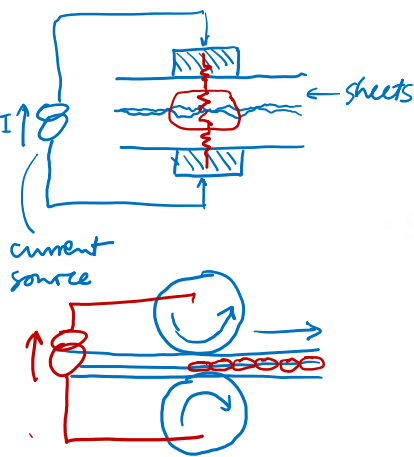
Electrodes are clamped across a stack of metal sheets to be welded. A current is passed through the stack, resistively heating the material between the electrodes. Material at the center of the stack heats up the most, because the thermal conduction path by which generated heat can escape to the surroundings is the longest there. The amount of heat energy generated can be precisely controlled, which makes this excellent for joining thin sheets that could be destroyed by a flame or an arc. The weld region is sometimes referred to as a nugget and the process is called a spot weld. Seam welding is a continuous form of spot welding whereby the sheet material passes between two conductive rollers and a series of overlapping spot welds are made in rapid succession. This process is suitable for creating sealed metal containers.
- Spot welding
- Sheets clamped between electrodes
- Current passes through
- Lozenge of material melts around the interface
- Seam welding
- Sheets pass between conductive rollers
- Current is pulsed
- Continuous weld is formed from overlapping spot welds
@ 16:48 & 17:20
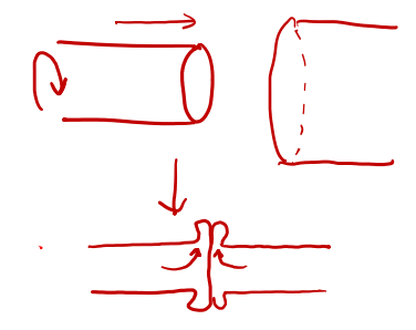
Friction (Stir) Welding #
Two components are rotated relative to each other at high speed under load (e.g. by mounting in a lathe). The heat generated by friction softens both components’ surfaces and they fuse.
- Two components undergo relative rotational motion in contact
- Heat resulting from friction at the interface leads to melting
- Components are pressed together until they fuse and cool
@ 20:48
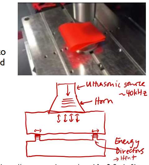
Ultrasonic Welding #
- A horn couples ~40 kHz vibrations into the components
- Oscillatory compression of the components translates to shear motion at the intended joint, and dissipation of energy as heat via friction
- “Energy directors” are features at the welded interface that lower contact area, and concentrate the loads, promoting material melting
Laser Welding #
- Focused laser beam provides the heat
- Readily automated weld paths
- Extremely precise welds (sub-mm-size) are possible
Electron Beam Welding #
- Focused beam of electrons (produced, e.g., by thermionic emission) is accelerated and steered towards workpiece by electromagnetic field reaching an electron energy of ~30-100 keV
- Loss of kinetic energy of electrons upon collision with workpiece generates heat
- Carried out in vacuum: as low as ~10-4 Torr (0.01 Pa)
- As with laser welding, extremely high-precision and small welds are possible
- Similar pros and cons as for e- beam melting additive m.$f_g$ vs selective laser melting
- Can make especially deep, narrow welds
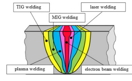
Typical Power Densities in Welding #
- Power density reaching material surface
| Type of welding | Typical power density (W/mm.$^2$) |
|---|---|
| Oxyacetylene | 10 |
| Arc | 50 |
| Resistance (electrical) | 1000 |
| Laser | 9000 |
| Electron beam | 10000 |
Modeling Heating in Welding #
- It is helpful to be able to predict the size of the weld pool and HAZ for given process parameters
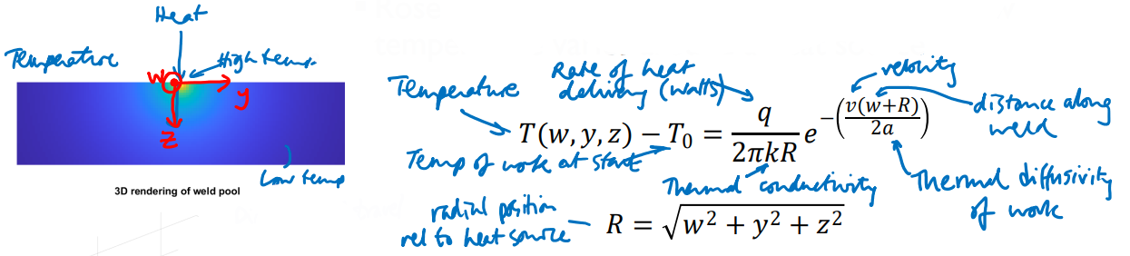
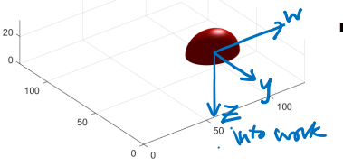
- Rosenthal developed a simple equation for how temperature varies around a heat source
$$T(w,y,z) - T_0 = \frac{q}{2\pi kR} e^{-\left(\frac{v(w+R)}{2a}\right)}; R = \sqrt{w^2 + y^2 + z^2}$$
- $T_0$: Temperature of work at start
- $v = \frac{dw}{dt}$: Velocity of beam
- $q$: Rate of heat delivery [Watts]
- $R$: Distance along weld
- $k$: Thermal conductivity
- $a$: Thermal diffusivity
- Time .$t_{8/5}$ for temperature to fall from 800 °C to 500 °C as the heat source passes is a key parameter for determining condition of HAZ: ideally about 10-25 s for carbon steels
Non-Welding Joining Methods #
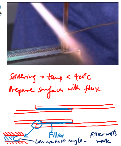
Other joining methods that involve introducing molten material to an interface are soldering and brazing, but in both these processes the gap-filling material is an alloy with a lower melting point than the components being joined. Soldering is used, for example, to join electrical components to printed circuit boards or to connect pipes in plumbing. Brazing is simply the term used for soldering when the filler melts above 400˚C. There is some inter-mingling of atoms of the filler and component material near the interfaces, which lends the joints strength, but soldered/brazed joints are still not as strong as welded ones can be.
Brazing #
- Filler is a metal or eutectic alloy with lower melting point than the work
- Advantages cf welding
- Good for thin walls
- Less heat required
- Suitable for joining dissimilar metals
- Avoid HAZ
- Use capillary forces to fill inaccessible joints
- Disadvantages cf welding
- Lower strength
- Appearance: differing colors
- Weakens at high service temperatures
- Applications
- Piping, preparing cutting tools e.g. cemented carbide
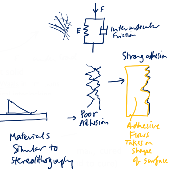
Types of adhesive #
- Pressure-sensitive
- Viscoelastic solid – forms under load
- Conforms to target solid
- Maximize van der Waals interactions
- Promotes mechanical interlocking
- Thermoplastic
- e.g. hot-melt glue
- Irreversible liquid-solid transition
- Radical-driven crosslinking: UV or thermally cured
- Epoxy resins (2-part; reacts when mixed to cure)
- Thermosetting silicones
- Cyanoacrylate:rapidly polymerizes in presence of water
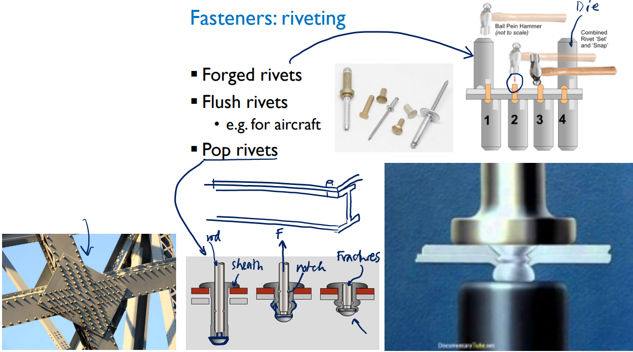
Fasteners: Riveting #
- Simple to process and automate
- Can’t be loosed by vibration (used in aircrafts)
- Typically cheaper (doesn’t need to be toleranced precisely)
- Doesn’t need the depth that threaded components do
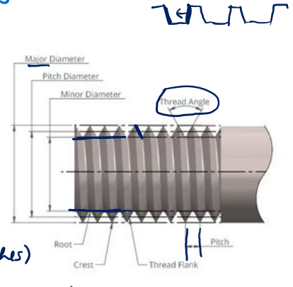
Fasteners: Screws and Bolts #
- Screw characterized by:
- Major, minor diameters
- Pitch (inverse of turns per inch), thread angle
- Length
- Conventional formats:
[Diameter]-[Turns / unit] x [Length]#4-40 x 0.5: Imperial; #4 diameter, 40 turns per inch, 0.5 length (in)1/4-20 x 5/8: Imperial; 1/4 …, 20 …, 5/8M3-0.50 x 10: Metric; 3 mm radius, 0.50 Pitch (mm), 10 length (mm)
- Various head styles available
- Square, counterbore, countersunk, round etc
- Important to protect against loosening in use
- Sprung, split washers
- Glue