As briefly mentioned before, the voltage and current sources covered so far have been independent sources, meaning they have a constant, fixed value. However,
dependent sources also generate currents and voltages but their output depends on some other “controlling” current .$i_x$ or voltage .$v_x$ in the circuit.
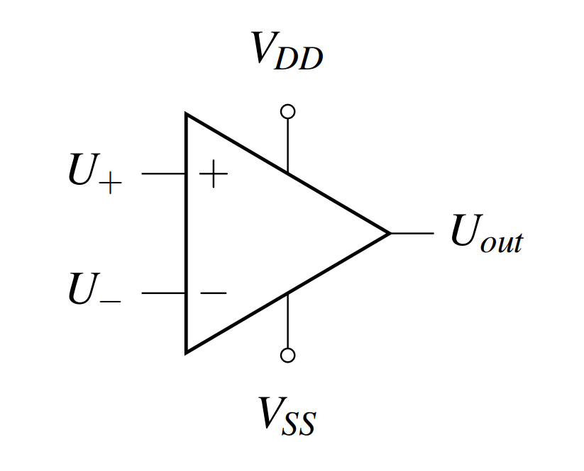
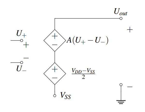
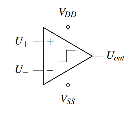
The larger $A$, the sharper/quicker the transition between $V_{SS}$ and $V_{DD}$
With KVL we can find $U_{out}$:
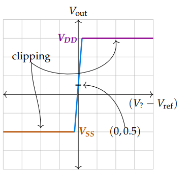
Except we can’t have $U_{out} > V_{DD}$ or less than $V_{SS}$ so we end up clipping $U_{out}$ – this is called railing
$$U_{out} = V_{SS} + \frac{V_{DD} - V_{SS}}{2} + A \Delta U$$
$$\dots = \frac{V_{DD} + V_{SS}}{2} + A \Delta U$$
$$\dots = \begin{dcases}
V_{SS} & \frac{V_{DD} + V_{SS}}{2} + A \Delta U < V_{SS} \\
V_{DD} & \frac{V_{DD} + V_{SS}}{2} + A \Delta U > V_{DD} \\
\frac{V_{DD} + V_{SS}}{2} + A \Delta U & \text{otherwise} \\
\end{dcases}$$
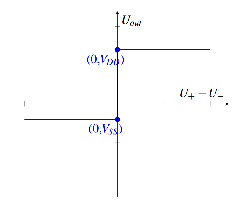
The sign of the output will indicate which input voltage is larger.
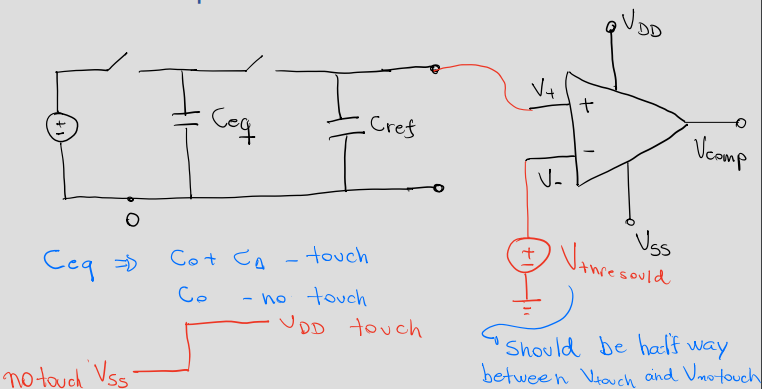
We often want to know whether $V_?$ is smaller or larger than $V_{ref}$ so we’ll set
$ V_- = V_{ref}$ and $V_+ = V_?$
The blue region is the (super narrow, and in the ideal case, perfectly vertical) linear region where the input actually has “space” to be amplified without clipping
For the vast majority of realistic inputs, the outputs sits at one of the rails (here, $V_{SS} = −2V$ and $V_{DD} = 3V$)
In this way, the sign of the output directly gives the relationship between $V_{?}$ and $V_{ref}$
Note that with zero input difference, the output voltage ($y$-intercept) sits at the rail-offset: $\left(0, \dfrac{V_{DD} + V_{SS}}{2} \right) = (0, 0.5)$
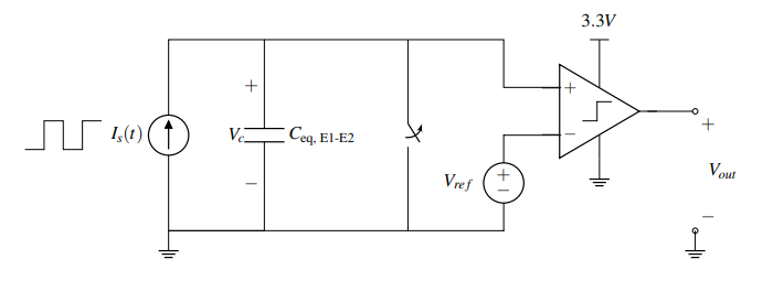
So how do we choose $V_{ref}$? We want our comparator to be high (on, $V_{out} = V_{DD}$) depending on touch (or lack thereof)
Thus we should set $V_{ref}$ to be between the peak of $V_C$ with a finger and the peak of $V_C$ without a finger
To be fairly
robust to noise/error, $V_{ref}$ should be exactly between the two peaks:
$$V_{ref} = \frac{V_{C, touch} + V_{C, no\ touch}}{2} = \dots = \frac{1}{2} \frac{C_{eq} + \Delta C}{C_{eq} + C_{ref} + \Delta C}\frac{C_{eq}}{C_{eq}+C_{ref}}$$
When there is a finger present, $V_C$ is always less than $V_{ref}$ so the output voltage is 0
Now every period of the current source cycle, $T$, we can measure if there is a finger touching this pixel
Label the voltages across all the capacitors. Choose whichever direction (polarity) you want for each capacitor - this means you can mark any one of the plates with the “+” sign, and then you can mark the other plate with the “−” sign. Make sure you stay consistent with this polarity across phases.
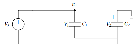
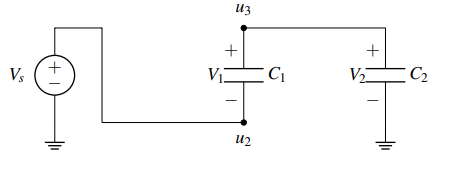
Draw the equivalent circuit during both phases. For this problem, phase 1: $\phi_1$ closed, $\phi_2$ open, and phase 2: $\phi_1$ open, $\phi_2$ closed. Also, label all node voltages on the circuit for both phases. No need to try and maintain the same names, since certain nodes of the phase 1 circuit might be merged or split in phase 2.
Identify all “floating” nodes in your circuit during phase 2. You can identify those nodes as the nodes connected only to capacitor plates, op-amp inputs or comparator inputs. These will be the nodes where we apply charge sharing.
In this case the only node that is floating during phase 2 is node $u_3$. (Node $u_2$ is connected to the voltage source, i.e. $u_2 = V_S$, and the 3rd node is the ground node)
For steps 4-6 we will examine each phase 2 floating node individually. Pick a floating node from the ones you found in step 3 and identify all capacitor plates connected to that node during phase 2. Then, calculate the charge on each of these plates in the steady state of phase 1. To do so, identify all nodes in your circuit during phase 1. Label all node voltages, and write the voltages across each capacitor as functions of node voltages (step 2 should help you with that). Do this according to the polarities you have selected. Then the charge is found as $Q = CV_C$ (where $V_C$ is the voltage across a capacitor).
Careful: The plate marked with the “−” sign will have $Q = -CV_C$ and the plate marked with the “+” sign will have $Q = CV_C$ stored onto them.
Careful: We assume here that you know all node voltages during phase 1. If you don’t, before starting this procedure calculate the node voltages you need using one of the previously introduced circuit analysis techniques (most likely KVL).
Looking at our single floating node we can see that the “+” plates of $C_1$ and $C_2$ are connected to it during phase 2. Let’s calculate the charge on these plates connected to the floating node $u_3$ during phase $\phi_1$, denoted $Q_{u3}^{\phi 1}$
Find the total charge on each of the floating nodes in the steady state of phase 2 as a function of node voltages using the same process as Step 4. Make sure you kept the polarity same and pay attention to the sign of each plate.
Apply conservation of charge. The charge in the steady state of phase 1 we calculated in Step 4, $Q_{u3}^{\phi 1}$, is the initial charge of phase 1. Charge must be conserved at a floating node, so the steady state charge of phase 2, $Q_{u3}^{\phi 2}$, should equal the
initial charge $Q_{u3}^{\phi 1}$. We can then write in terms of the unknown(s).
Repeat steps 4-6 for every floating node. This will give you one equation per floating node (i.e. if you have $m$ floating nodes you will have $m$ equations). You can then solve the system of equations to find the node voltages during phase 2 (unknowns).
In this problem we did not go through step 7 since we only had one floating node during phase 2. This means we have only one unknown node voltage ($u_3$) for which we solved using our single equation from Step 6.
Example 2 on page 4 has multiple floating nodes.
A node that is floating during phase 2 is not necessarily floating during phase 1. In fact, it could have been two separate nodes during phase 1 depending on how your switches are configured. We only care about the floating nodes during phase 2 since those are the nodes with unknown voltages. What about floating nodes during phase 1? You should be able to calculate the voltage of these nodes based on the initial condition of the circuit and the circuit techniques that you have learned so far (most likely KVL).
When handling charge sharing problems you should avoid using any parallel or series capacitance formulae that you have learned. Any simplification of the circuit might lead to mistakes since the circuit in different phases is configured differently and some capacitors placed in series during one phase may be in parallel or even not connected at all in another phase!


When there is a finger present, $V_C$ is always less than $V_{ref}$ so the output voltage is 0
Now every period of the current source cycle, $T$, we can measure if there is a finger touching this pixel
Label the voltages across all the capacitors. Choose whichever direction (polarity) you want for each capacitor - this means you can mark any one of the plates with the “+” sign, and then you can mark the other plate with the “−” sign. Make sure you stay consistent with this polarity across phases.