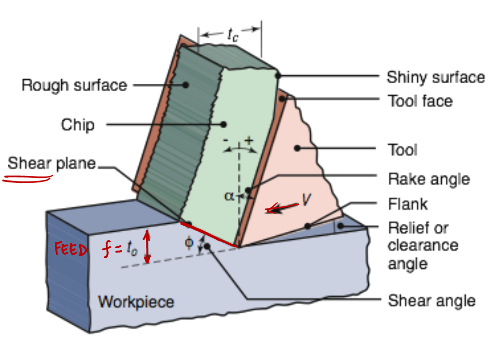
To analyze chip formation, we consider the 2D y–z plane, with the x axis out of the page
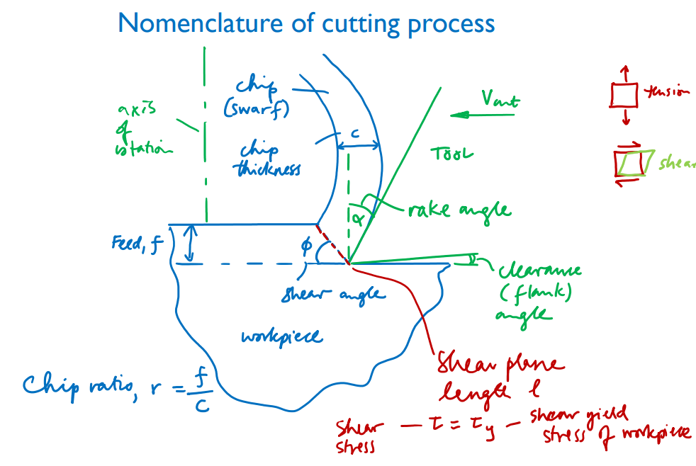
We assume that all plastic deformation occurs in a single plane, the shear plane, which is oriented at an shear angle .$\phi$, to the direction of relative motion .$V_\text{cut}$ of the tool and work.
The shear plane meets the sharp edge of the cutting tool at the bottom of the cut.
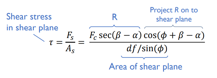
The area of the shear plane is .$fd / \sin \phi$ where .$f$ is the feed (also denoted by .$t_0$ in some texts), and .$d$ is the cut depth (out of the page; also denoted by .$w$ in some texts).
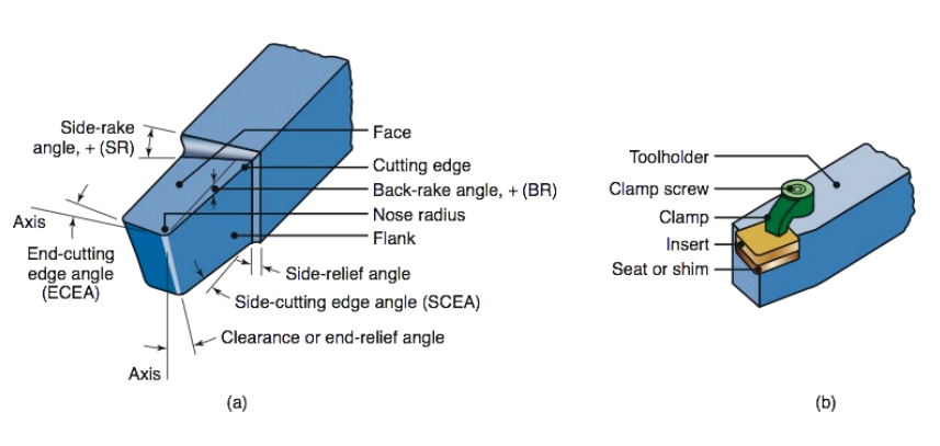
The tool itself has a carefully designed shape. Its front face is positioned at an angle .$\alpha$, the rake angle, from a plane normal to the direction of relative tool–workpiece motion.
As we will see, the rake angle will always be chosen to be greater than zero, to ensure a clean cut and to reduce the amount of mechanical work needed to produce a cut.
The flank angle, meanwhile, is that between the bottom of the tool and the post-cutting workpiece surface.
The flank angle needs to be greater than zero to reduce friction and any resulting scratching or fusion between the tool and the freshly machined surface.
We can control the rake and flank angles by manufacturing a cutting tool to our specifications.
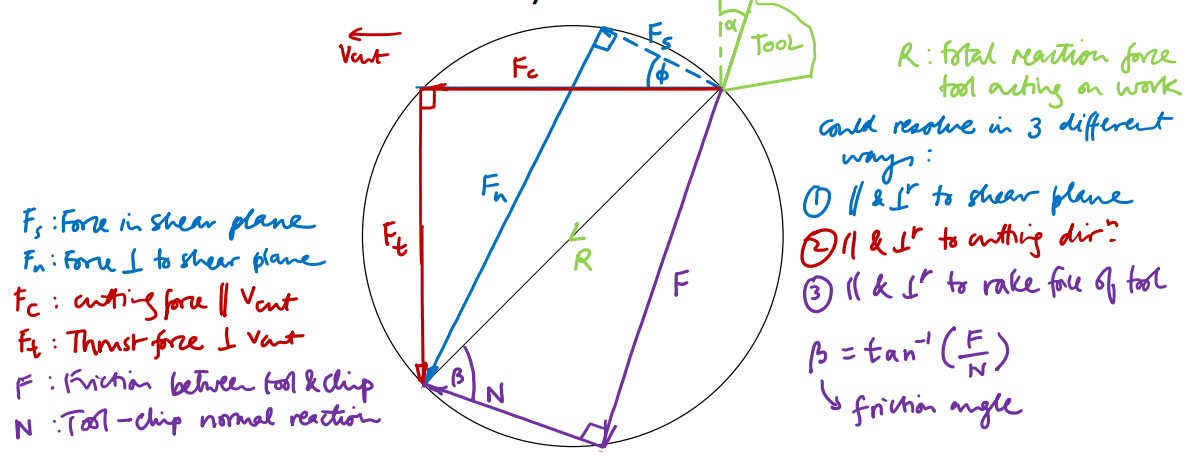
Force diagram that resolves the reaction force exerted by the tool on the work
It is important to consider the magnitudes and directions of the forces that are exerted by the tool on the workpiece during cutting. These forces determine the torque required to rotate the work, the amount of elastic distortion of the work or the lathe that might occur during cutting (potentially leading to inaccuracies in the manufactured component), and also whether the tool will experience a load large enough to fracture it.
One way to analyze these forces is with Merchant’s Circle. This Circle is a graphical device developed in the 1940s by Eugene Merchant to visualize cutting loads. The circle itself does not represent the shape of the work being cut. This is a force diagram – i.e. the lengths of lines represent magnitudes of forces, not physical distances. The directions of the lines do correspond to actual orientations in space. The horizontal axis corresponds to the cutting direction.
We can use Merchant’s Circle to understand how to design and optimize the cutting process. For example, suppose that we have obtained an estimate of .$\phi$ from experimental measurements of the chip thickness. We could then use the trigonometrical relationships illustrated in Merchant’s Circle, substituting our estimated .$\phi$ and our known .$\alpha$ for the tool, to estimate the friction angle .$\beta$, which would be difficult to measure directly. This approach might be used to compare the effect on friction angle of various candidate tool materials, coatings, or lubricants.
Relating cutting geometry to cutting forces
Material properties link the geometry of the tool and cutting path to the forces involved.
The material being cut needs to exceed its shear yield stress to start deforming (cutting) and creating a chip.
If the material exceeds its ultimate shear strength, the chip becomes more likely to fragment into pieces as it forms (which may help clear waste material away).
However, the more strain involved in chip formation for a given material, the more work has to be invested in the cutting operation.
Therefore designing the cutting operation to limit shear strain can help to limit cutting energy required.
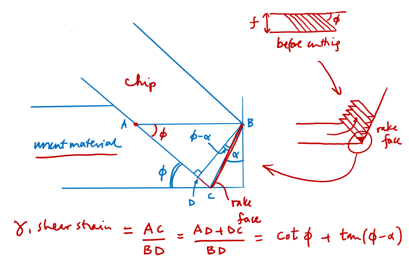
Since we wish to limit the amount of shear strain, .$\gamma$, occurring during cutting, we need to understand how it depends on parameters that we can control.
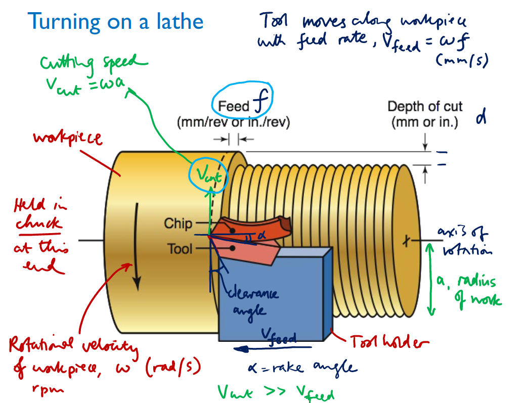
Parameters we control: .$f, V_\text{cut}, d, \omega, \alpha$.
Parameters we don’t directly control, but can measure: .$c, F_c , F_t$
Parameters we don’t directly control and are hard to measure directly: .$\phi, \beta$, and forces other than .$F_c$ and .$F_t$
Next, we show (via geometry) how shear strain .$\gamma$ depends on shear angle .$\phi$ (which is hard to measure directly) and on rake angle .$\alpha$ (which is known in advance).
To predict shear angle .$\phi$, we then have two options:
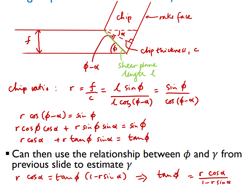
Measure chip thickness, .$c$, and use geometry to work out .$\phi$ in terms of .$f, c$ and .$\alpha$, or
Use Merchant’s shear angle relationship to express .$\phi$ in terms of .$\alpha$ and .$\beta$, and find .$\beta$ by measuring cutting and thrust forces .$F_c$ and .$F_t$ (e.g. by force sensors on the cutting tool holder)
Then, we can take action to control shear strain and cutting force.
If we did not have any experimental estimate of .$\phi$ (since it’s a function of the material’s properties) but we did have an estimate of .$\beta$ and knowledge of rake angle .$\alpha$ (since we can control the tool we use(’s rake angle)) and the shear strength of the work material, .$\tau_y$, we could use Merchant’s shear angle relationship to predict both .$\phi$ and the cutting force.
We can measure a chip to get .$c$
Can then use the relationship between .$\phi$ and .$\gamma$ to estimate .$\gamma$ Merchant’s shear angle relationship
This is to show how we can do process diagnosis if we understand each step of the process and how they relate to one another
Understand merchant forces, shear/friction angle, the physical relationship between these angles, and terms (cutting depth, feed (cut amount per rotation), feed rate (speed moving tool along machine))
The total reaction force exerted by the tool on the work, .$R$, can be resolved in any of three useful coordinate frames:
The first frame is defined by the cutting direction. .$F_c$ is the cutting force, the force in the direction of relative motion of the tool and work. This force is important because the mechanical work done by the lathe is equal to the cutting force times the distance moved in the direction of cutting. The force perpendicular to the cutting force, the thrust force, .$F_t$, can contribute to bending of the work during turning and can become problematic and lead to vibration, particularly with long slender workpieces if they are not supported at both ends.
The second frame is defined by the rake (front) face of the tool, and decomposes the reaction force into a frictional force .$F$ parallel to the rake face, and a normal reaction component .$N$. These loads are related by the friction angle: .$\beta = \arctan (F/N)$ where .$F/N$ is the coefficient of friction between the chip and the tool. This coefficient can be considerably larger than 1, particularly if chip material bonds to the front of the tool (leading to a built-up edge) and chip–tool sliding involves plastic deformation of the chip. Ideally .$\beta$ will be as small as possible, which can be achieved with liquid lubrication of the cutting location and/or by special tool coatings which make it smooth and reduce the coefficient of friction.
The third frame is defined by the shear plane, and is composed of the shear force .$F_s$ which acts within the shear plane, and the normal component .$F_n$
We assume that shear stress equals the shear strength of the workpiece material in the shear plane, and that shear stresses are lower elsewhere in the material.
Also assume that the value of the shear angle .$\phi$ is naturally such that the shear strength, .$\tau_y$, of the workpiece material is reached in the shear plane at the lowest possible cutting force .$F_c$.
If we know the material’s shear strength, the friction angle .$\beta$, and the shear angle .$\phi$, we can (roughly) estimate the required cutting force .$F_c$.
Need to solve for .$\phi$ in terms of parameters we can control: .$\alpha$ (directly through tool geometry) and .$\beta$ (indirectly through lubrication).
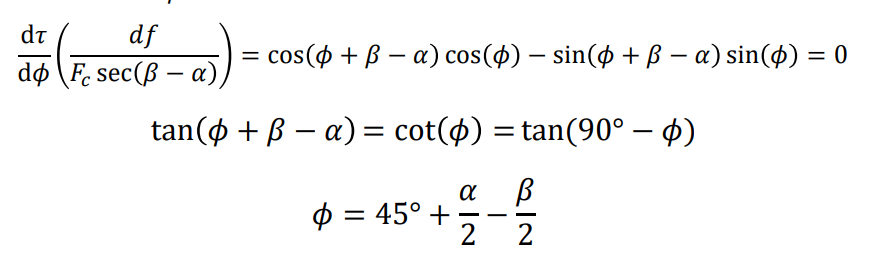
To find value of .$\phi$ for maximum shear stress at a given .$F_c$, set derivative .$\frac{d\tau}{d\phi}$ to zero and solve:
Aside: This equation assumes that all deformation occurs in the sheer plane
The lower the friction angle, the higher the sheer angle, requiring larger cutting forces
To estimate .$\beta$, we can measure .$F_c$ and .$F_t$ and use the force-resolving circle, and then substitute into the expression for .$\phi$:
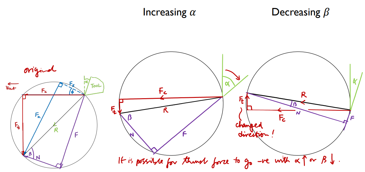
Increasing the rake angle .$\alpha$ (via tool design) and lowering friction angle .$\beta$ (by application of an appropriate lubricant/coolant – e.g. water/oil mixture) both help to increase shear angle, reducing the area of the shear plane.
However there are limits: for instance, if .$\alpha$ becomes too large, .$F_t$ may become negative in which case the tool would dig into the workpiece and result in a very poor finish.
There’s a limit to how high .$\alpha$ can reasonably be, though. If it becomes so large that the angle enclosed at the tool tip is extremely sharp, the tool will become highly susceptible to cracking.
Moreover, at very large .$\alpha$ the thrust force may change direction and tend to pull the tool into the work, leading to vibration and a very poor finish.
Examples of process changes
This model is an approximation; alternative models exist Merchant’s circle: examples of process changes
The larger .$\phi$, the shorter the shear plane and the smaller the cutting force is expected to be for a given feed, cut depth and material (reducing the cutting force is desirable). If .$\phi \approx 0$, the shear plane would be large and the cut would be rough.
As a rule of thumb, if the angle between the shear plane and the rake face of the tool is about 90°, cutting will be of reasonably high quality as long as adequate lubrication and a reasonable cutting speed are used.
Meanwhile, knowledge of .$\gamma$ can help give a picture of how much plastic deformation is occurring in the chip between the moment of first yield and the chip leaving the cutting tool.
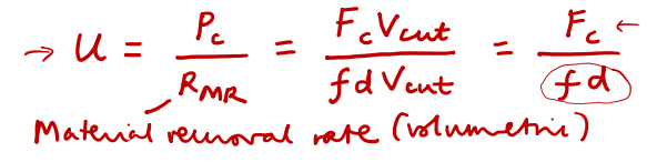
The above analysis relies on having knowledge of multiple geometrical parameters, the friction coefficient, and material properties such as shear strength. These values will often not be available; another approach is to characterize metal cutting operations with a specific energy value, which is the energy required to remove a unit volume of material from the work.
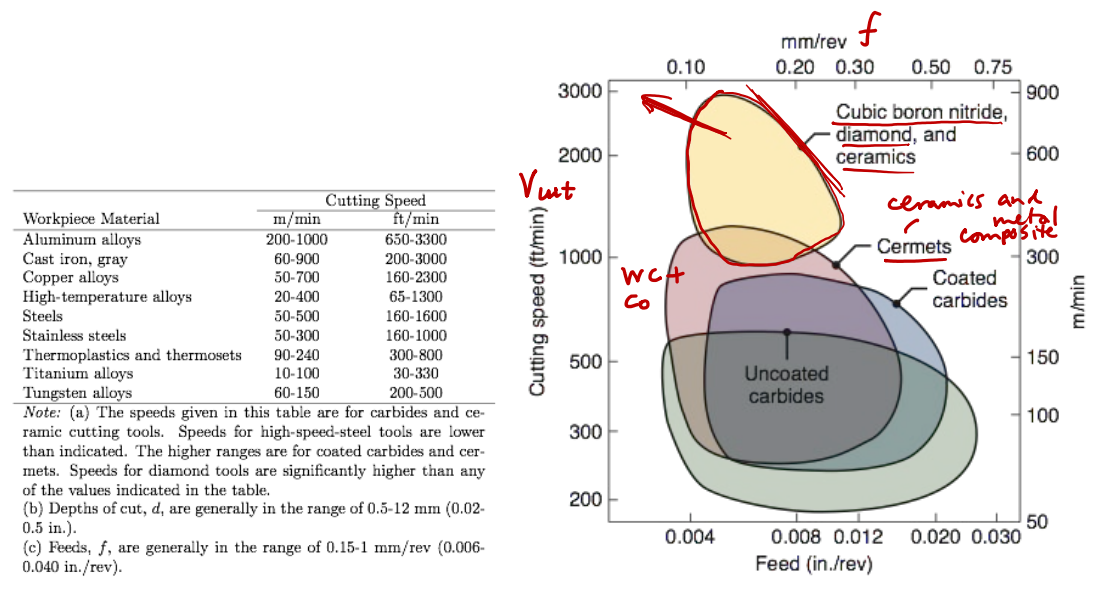
Specific energies are usually reported with quite a wide range (e.g. 0.4–1.1 J/mm.$^3$ for aluminum alloys) to take into account the variability of tool–material friction and tool geometries that might be used.
Different workpiece materials are associated with different specific energies, .$U$ (J/mm.$^3$): the work that must be done per unit volume material removed.
However, these energies, which are widely tabulated in handbooks, provide a simple way to relate cutting speed, force and power. The cutting power is simply the product of material removal rate and specific energy. The material removal rate can be computed as the product of cutting speed, feed and cut depth.
Broadly speaking, the harder the tool and the softer the workpiece, the larger the feeds and speeds that can be successfully used. The ductility of the workpiece (strain at fracture) also plays a role in determining suitable feed and speed.
Not all of the cutting power will go straight into plastic deformation of the work material. In a typical process about 30% of the work done would be dissipated as tool–chip friction. Additionally, the electrical power input to the lathe will exceed the cutting power required, because the motor will not be perfectly efficient and there will also be some mechanical losses in the lathe.
.$U$ approximately folds in work done in the shear plane, work done against friction, and mechanical losses in the lathe – hence each material has a quite wide range for .$U$
Example values of .$U$ (J/mm.$^3$):
Aluminum alloys: 0.4 – 1.1
Titanium alloys: 3.0 – 4.1
Steels: 2.7 – 9.3
Expression linking .$U$, cutting power .$P_C$, and geometry:
Since .$F_C$ depends on the tool, we can find the span of possible .$f, d$ values with the equation above (which need to be sufficiently great to remove material from the work)
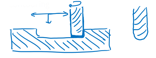
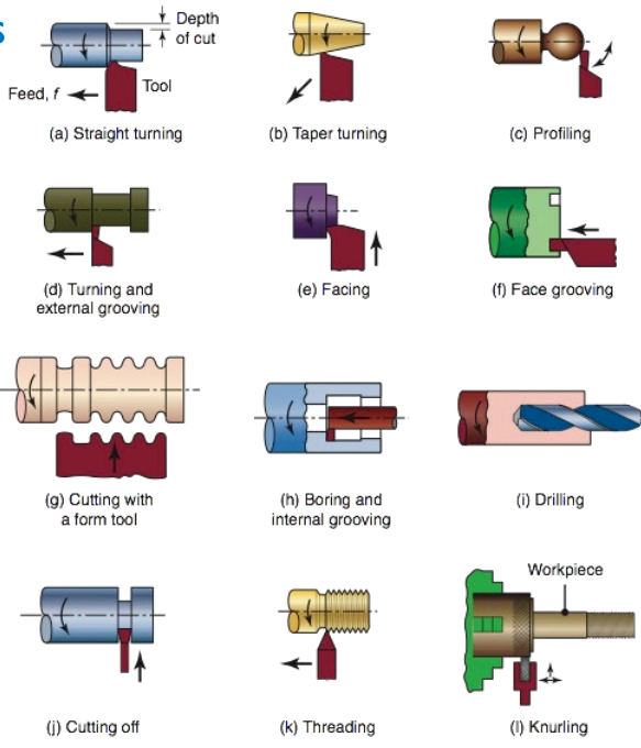
We have discussed the concepts of shear plane, rake angle and cutting power, etc, in the context of lathe turning
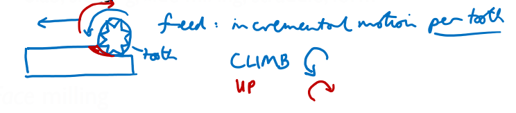
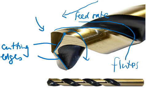
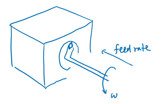
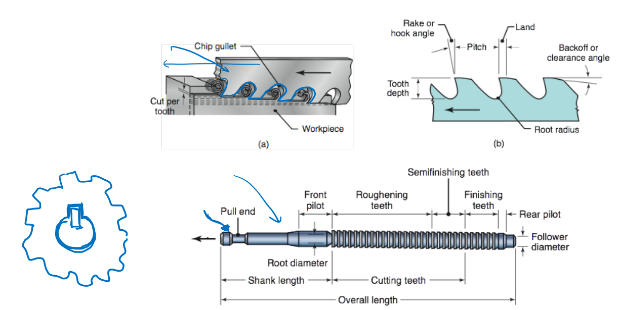
But these concepts apply across a whole range of metal-cutting processes, including facing processes on a lathe, as well as drilling, milling, planing, and even processes that use tools with many small cutting edges, such as sawing and rasping.
In all of these processes the cutting edge shape is optimized to reduce the amount of mechanical work done to remove material, and give a clean, smooth cut.
The basic requirement of any cutting tool is that it must be made of a material that is harder than the material it is cutting.
For cutting many metals and alloys, we can use high speed steel (HSS), which is a hardened steel containing tungsten, chromium and vanadium as alloying elements.
The cutting speeds that are possible with HSS, however, are lower than can be achieved with harder, higher-melting-point, tool materials. An example of such a material would be tungsten carbide.
Cutting tool materials, being very hard, are very challenging to machine, and so are made either by grinding or by powder metallurgy, where powder mixtures are pressed in a mold into the shape of the required tool insert and are then baked to fuse the powder.
We say tool insert because the objects made by powder metallurgy are small square items that are mounted into a larger holder.
The inserts usually have multiple usable edges, so as soon as one of them is blunt or fractured, the insert can simply be rotated in the holder without re-aligning the tool in the machine.
An example of a tool material produced by powder methods is “cemented carbide” which is hard tungsten carbide powder bound together with cobalt.
Cemented carbides are harder wearing than conventional high-speed steel and easier to produce than pure tungsten carbide tools.
Coatings are also important in tool fabrication. Titanium nitride and diamond-like carbon are examples of coatings that reduce chip–tool friction, in part by reducing the surface roughness of the tool
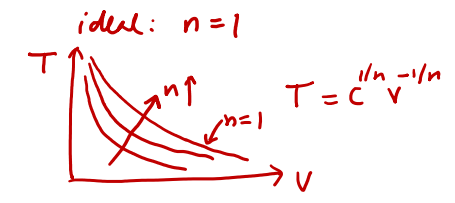
The useful lifetime of a cutting tool is a function both of the material and of the cutting velocity at which it operates.
This is because as the cutting speed increases, the rate of frictional heat dissipation rises, heating and softening the tool material, and enabling it to erode more quickly:
.$n < 1$ and predominated by the melting temperature of the tool material
Smaller .$n$ values indicate that cutting tool lifetime falls more rapidly as cutting velocity increases than materials with .$n$ approaching 1.
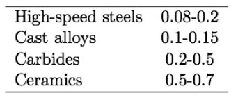
Example .$n$ values:
One advantage of using a tool material that can withstand a higher cutting speed is that one can reduce processing time. Another potential advantage is to be able to reduce the feed while not lengthening the total processing time. Smaller feeds can enable smoother finishes to be achieved, so finishing cuts will tend to have smaller feeds than roughing cuts (which remove large amounts of material quickly at the start of a turning process)
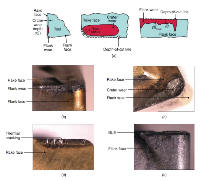
(a) Schematic illustration of a right-hand cutting tool for turning. Although these tools have traditionally been produced from solid tool-steel bars, they are now replaced by inserts of carbide or other tool materials of various shapes and sizes, as shown in (b). The insert is the actual cutting feature.
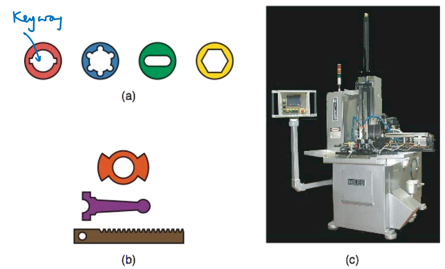
(a) Typical parts finished by internal broaching. (b) Parts finished by surface broaching. The heavy lines indicate broached surfaces; (c) a vertical broaching machine.
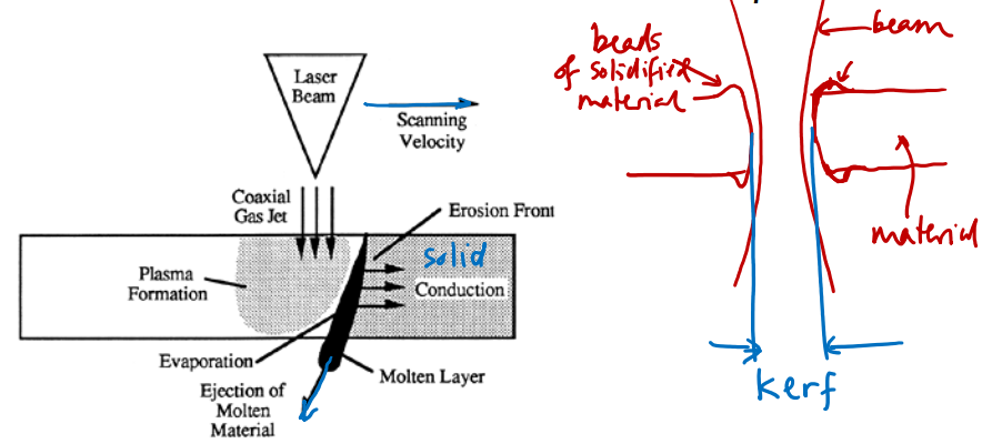
In laser cutting, an intense beam of light imparts heat locally to the material and converts the solid either to liquid or directly to vapor to form an edge
Where this melted material goes (may) matter depending on the job
Extremely quick
With the right type of laser you can cut many materials
In ablation, a laser beam vaporizes material from the surface of a component to shape it without cutting all the way through it.
A thin band of material is removed: the kerf
Has some thickness, maybe a thousandth, which may matter
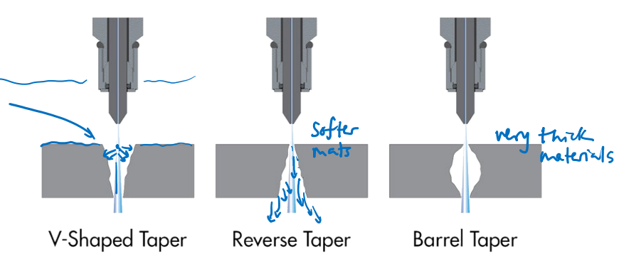
The cut isn’t completely vertical – intensity isn’t uniform, and beam may not be completely orthogonal (and even then there is some geometry of the
focal-spot)
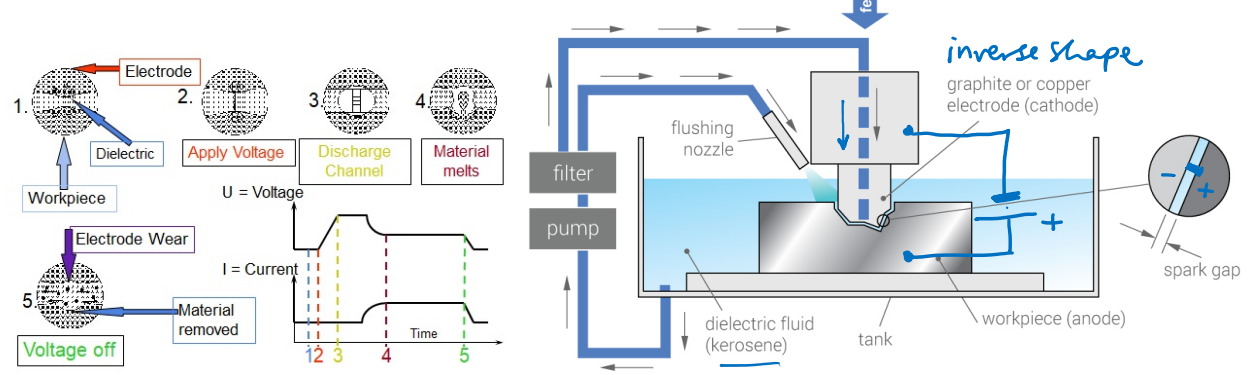
An electrical field is applied between a high-melting-point electrode (which creates sparks, plasma) and the material that that is to be shaped is usually submerged in water.
The gap breaks down electrically and a high current flows, heating and vaporizing the work material.
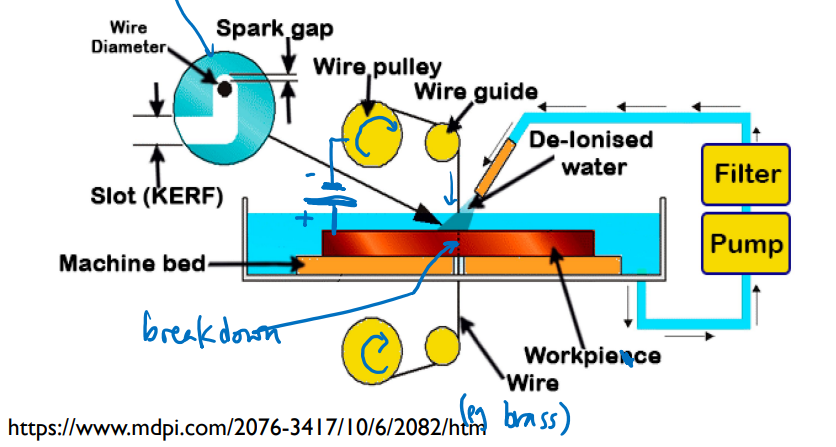
The electrode might be made of a wire (for profiling operations) or might be a custom-shaped electrode (e.g. made of graphite) to enable parallel transfer of a complex geometries to a workpiece.
Used when you require extreme precision
Wire has a constant width, there’s no focusing issues like with laser cutting
 We can use Merchant’s Circle to understand how to design and optimize the cutting process. For example, suppose that we have obtained an estimate of .$\phi$ from experimental measurements of the chip thickness. We could then use the trigonometrical relationships illustrated in Merchant’s Circle, substituting our estimated .$\phi$ and our known .$\alpha$ for the tool, to estimate the friction angle .$\beta$, which would be difficult to measure directly. This approach might be used to compare the effect on friction angle of various candidate tool materials, coatings, or lubricants.
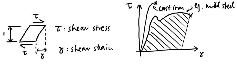
 To find value of .$\phi$ for maximum shear stress at a given .$F_c$, set derivative .$\frac{d\tau}{d\phi}$ to zero and solve:
 This model is an approximation; alternative models exist Merchant’s circle: examples of process changes