To have a current, we need an emf (electromotive force) device to transform one type of energy (chemical, mechanical, light) into electric energy
The term “electromotive force” is a misnomer: it does not refer to a “force,” which is measured in newtons. To avoid confusion, we use the abbreviation, emf.
EMF of the Source: The potential difference between the terminals of a source when no current flows to an external circuit
.$\mathscr{E}$ is used for emf and it’s units is (V)olts
We use Kirchhoff’s two rules when circuits get too complex for trivial analysis
1. Junction Rule:
At any junction point, the sum of all currents entering the junction must equal the sum of all currents leaving the junction.
That is, what goes out must come back in
Based on conservation of electric charge
Mathematically,
$$\sum_{k=1}^{n} I_k = 0$$
.$n$ is the total number of branches with currents flowing towards or away from the node.
The current entering any junction is equal to the current leaving that junction: .$I_2 + I_3 = I_1 + I_4$
2. Loop Rule:
The sum of the changes in potential around any closed loop of a circuit must be zero.
That is, what goes up must come back down
There is as much up as there is down
At the battery, the gain/loss on each terminal cancel one another along the closed circuit path
Based on conservation of energy
Mathematically,
$$\sum_{k=1}^{n} V_k = 0$$
.$n$ is the total number of voltages measured.
The sum of all the voltages around a loop is equal to zero: .$V_1 + V_2 + V_3 + V_4 = 0$
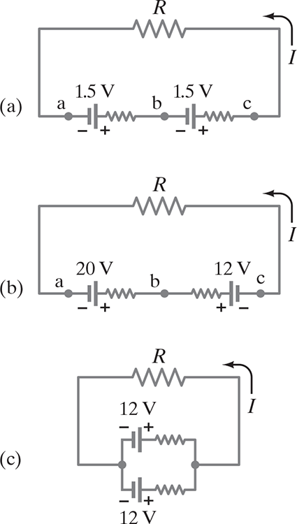
26.4 EMFs in Series and Parallel; Charging a Battery
#
(a) Two similarly arranged batteries in a series sum their voltages; e.x. 3V
(b) Two oppositely arranged batteries in a series subtract their voltages; e.x. 8V
How battery charging works
The 20V source is charging up the 12V battery
Because of it’s greater voltage, the 20V is forcing charge back into the 12V
(c) Two batteries in parallel, which if the emfs are the same, can provide more energy when large currents are needed.
Each of the cells in parallel has to produce only a fraction of the total current, so the energy loss due to internal resistance is less than for a single cell
Thus, the batteries will drain less quickly.
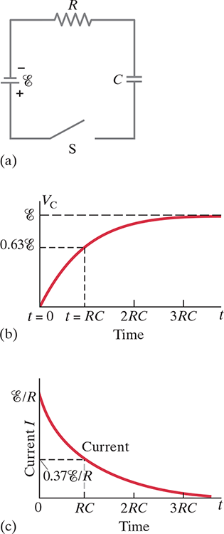
26.5 RC Circuits: Resistor & Capacitor in Series
#
RC Circuits differ in that they have varying current
After the switch .$S$ closes in the RC circuit shown in (a), the voltage across the capacitor increases with time as shown in (b), and the current through the resistor decreases with time as shown in (c).
(a) When closed, the current starts flowing through the circuit from the negative terminal through .$R$ and accumulate on the upper plate of the capacitor which creates potential difference equal to .$V_C = Q/C$
Current is then reduced because of this opposing voltage on the capacitor
(b) Eventually, the potential equals the emf, .$\mathscr{E}$, and then no current flows and no potential difference across the resistor
Potential difference, .$V_C$, across the capacitor is equal to the charge on it, .$V_C = Q/C$
Because charge increases with time, so does voltage until this point
The emf .$\mathscr{E}$ of the battery will equal the sum of the voltage drops across the resistor and the capacitor:
$$\mathscr{E} = IR + \frac{Q}{C}$$
.$R$ is total circuit resistance, including battery
.$I$ is current at all points in the circuit at any instant
.$Q$ is the charge of the capacitor at that same instant
Notice: .$\mathscr{E}, R, C$ are constants, .$Q, I$ are functions of time
(c) As charge builds up on the capacitor, the current decreases exponentially in time with a time constant .$\tau$ equal to .$RC$
The rate at which charge flows thorough the resistor (.$I = dQ/dT$) is equal to the rate at which charge accumulates on the capacitor:
$$ \mathscr{E} = \bigg(\frac{dQ}{dt}\bigg)R + \frac{1}{C}Q$$
This can then be used to find an equation of .$Q$:
$$ \Longrightarrow \frac{dQ}{C\mathscr{E} - Q} = \frac{dt}{RC} \Longrightarrow \int_0^Q \frac{dQ}{C\mathscr{E} - Q} = \frac{1}{RC}\int_0^t dt$$
$$ \Longrightarrow \ln\bigg(1 - \frac{Q}{C \mathscr{E}}\bigg) = - \frac{t}{RC} \Longrightarrow 1 - \frac{Q}{C\mathscr{E}} = e^{-t/RC}$$
$$ \Longrightarrow Q = C\mathscr{E}(1-e^{-t/RT}) = Q_0 (1-e^{-t/RT})$$
.$Q_0 = C \mathscr{E}$ represents the maximum charge on the capacitor
.$Q_0 \neq \text{charge $(Q)$ at $t = 0$}$
The potential difference across the capacitor is .$V_C = Q/C$ so the maximum value is
$$ V_C = \mathscr{E}(1-e^{-t/RC})$$
.$\tau = RC$ is the axis units on graph (b) and is aptly called the time constant of the circuit
Represents the time required for the capacitor to reach .$(1-e^{-1}) = 0.63 = 63\text{%}$ of its full charge and voltage
Also represents the time for the current to drop to .$1/e \approx 0.37$ of it’s initial value
Thus, it measures how quickly the capacitor becomes charged
We use this as a measurement since the maximums only occur as we take .$t \to \infty$, but these values reach 86% of the way in .$2RC = 2\tau$, 95% in .$3\tau$, 98% in .$4\tau$, so on
The current in the circuit at any time can be found by differentiating the following:
$$I = \frac{dQ}{dt} = \frac{\mathscr{E}}{R}e^{-t/RC}$$
This is an exponential decay function: when .$t = 0$, the current is largest because there is no charge on the capacitor to impede it
That is, .$I = I_0 = \mathscr{E}/R$
As charge builds up, the current decreases exponentially in time (as shown in (c))
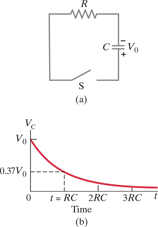
Now imagine the opposite case; we start fully charged at .$Q_0$ with voltage .$V_0$ and have to discharge through resistance .$R$
The voltage across the resistor at any instant equals that across the capacitor:
$$V = IR = \frac{Q}{C}$$
We can use this to find the functions for both .$Q_0$ and .$V_C$:
$$ - \frac{dQ}{dt} R = \frac{Q}{C} \Longrightarrow \frac{dq}{Q} = - \frac{dt}{RC}$$
$$ \ln \frac{Q}{Q_0} = - (t/RC) \Longrightarrow Q = Q_0 e^{-t/RC}$$
$$ \dots \Longrightarrow V_C = V_0 e^{-t/RC}$$
For the RC circuit shown in (a), the voltage .$V_C$ across the capacitor decreases with time, as shown in (b), after the switch S is closed at .$t = 0$. The charge on the capacitor follows the same curve because .$Q \propto V_C$
$$$$
$$$$
.$V_0 = Q_0 / C$ is the initial voltage, related to initial charge
We can see the charge on the capacitor, thus the voltage across it, decreases exponentially in time
Current is found to be
$$I = - \frac{dQ}{dt} = \frac{Q_0}{RC}e^{-t/RC} = I_0 e^{-t/RC}$$
The charge on the capacitor, the voltage across it, and the current in the resistor all decrease to 37% of their original value in one time constant .$t = \tau \ RC$
Current above .$\text{10 mA}$ cause severe contraction of muscles (may not be able to let go of source)
Current above .$\text{80-100 mA}$ that passes through the torso (passing through the heart for a second) will cause ventricular fibrillation (heart stops pumping blood properly)
It’s current that harms, even though voltage drives the current
The seriousness of a shock depends on the current and thus the applied voltage and the effective resistance of the body
More voltage shocks, more current kills
Wet skin has resistance of .$10^3 \Omega$ while dry skin is around .$10^5 \Omega$
Measuring is hard to do both precisely and consistently
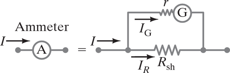
Ammeters measure current (amps) and voltmeters measure potential difference or voltage (volts)
An analog ammeter or voltmeter uses a galvanometer
The full scale sensitivity, .$I_m$, is the electric current required to make the needle deflect a full scale; typically .$50 \mu\text{A}$
An ammeter is a galvanometer in parallel with a shunt resistor with low resistance, .$R_\text{sh}$
A voltmeter is a galvanometer in series with a resistor with high resistance, .$R_\text{ser}$
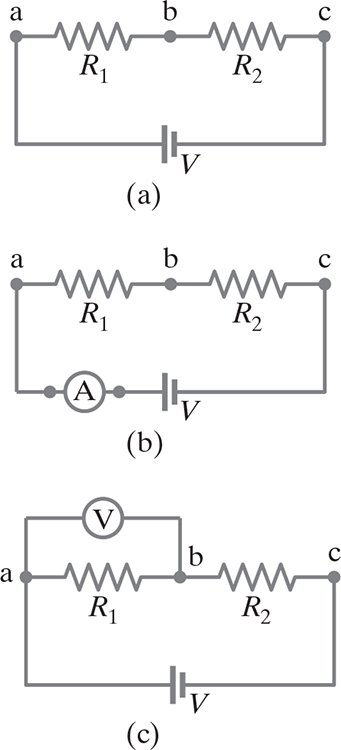
(b) Because an ammeter is used to measure the current flowing in the circuit, it must be inserted directly into the circuit, in series with the other elements. The smaller its internal resistance, the less it affects the circuit.
(c) A voltmeter is connected “externally,” in parallel with the circuit element across which the voltage is to be measured. It measures the potential difference between two points. Its two wire “leads” (connecting wires) are connected to the two points.
Only .$R_1$ is being measured above
If the resistance of a voltmeter is much higher than the resistance of the circuit, it will have little effect and its readings can be more accurate
At least to the manufactured precision of the meter, which for analog meters is typically 3% to 4% of full-scale deflection.
Sensitivity: The sensitivity of a voltmeter is specified on its face as, for example, .$10,000\ \Omega/\text{V}$. Then on the .$5\text{V}$ scale, the voltmeter would have a resistance given by .$\text{(5V)(10,000 $\Omega$/V) = 50,000 $\Omega$}$
Even an ammeter can interfere with a circuit, but the effect is minimal if its resistance is much less than that of the circuit as a whole.
For both voltmeters and ammeters, the more sensitive the galvanometer, the less effect it will have on the circuit.
The current entering any junction is equal to the current leaving that junction: .$I_2 + I_3 = I_1 + I_4$
The sum of all the voltages around a loop is equal to zero: .$V_1 + V_2 + V_3 + V_4 = 0$