Every magnet has two ends or faces called poles which are where the magnetic field is strongest
If a magnet is suspended so it can move freely, one pole will point north
Aptly, this side is called the north pole
Magnetic poles aren’t like electric charge: Positive or negative charge can easily be isolated, but we can never isolate a magnetic pole
That is, if you cut a magnet is half you don’t obtain isolated north and south poles.
Rather, you end up with two new magnets each with north and south poles
Ferromagnetic: Materials with a strong magnetic effect i.e. iron, cobalt, nickel, gadolinium
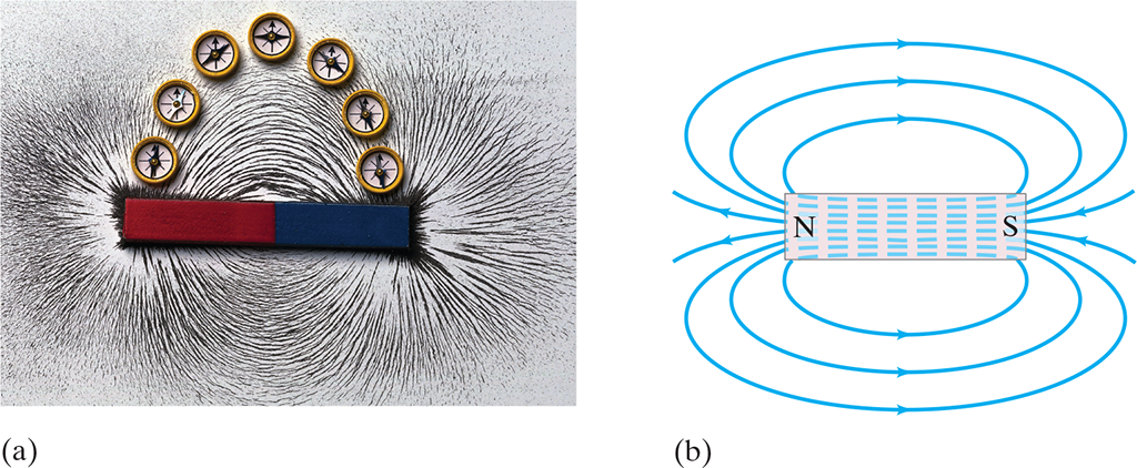
Similar to how we picture electric fields around a charge, we can picture magnetic fields surround a magnet
Field lines should be drawn so that (1) the direction of the magnetic field is always tangent to a field line everywhere and (2) the number of lines per unit area is proportional to the magnetic field strength
(a) Visualizing magnetic field lines around a bar magnet, using iron filings and compass needles. The red end of the bar magnet is its north pole. The N pole of a nearby compass needle points away from the north pole of the magnet. (b) Diagram of magnetic field lines for a bar magnet.
Earth’s magnetic poles are not exactly through the geographic pole (axis of rotation)
The angular difference between the direction of the compass needle (which points along the magnetic field lines) at any location and true (geographical) north varies between .$0 - 20^\circ$ with location
Earth’s magnetic field at most location is not tangent to earth’s surface
Angle of Dip: The angle that Earth’s magnetic field makes with the horizontal at any point
The Earth acts like a huge magnet. But its magnetic poles are not at the geographic poles (on the Earth’s rotation axis).
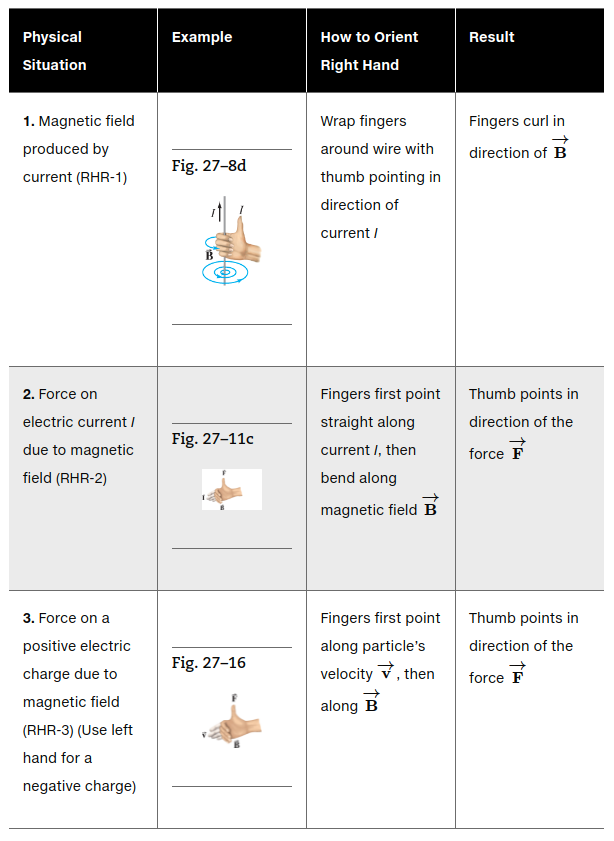
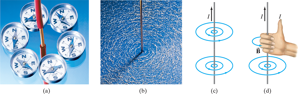
(a) Deflection of compass needles near a current-carrying wire, showing the presence and direction of the magnetic field. (b) Iron filings also align along the direction of the magnetic field lines near a straight current-carrying wire. (c) Diagram of the magnetic field lines around an electric current in a straight wire. (d) Right-hand-rule-1 for remembering the direction of the magnetic field: when the thumb points in the direction of the conventional current, the fingers wrapped around the wire point in the direction of the magnetic field. (.$\vec B$ is the symbol for magnetic field).
27.3 Force on an Electric Current in a Magnetic Field
#
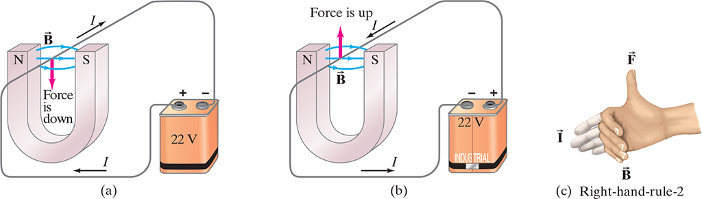
By Newton’s third law, we can see that a magnet exerts a force on a current-carrying wire
The direction of the force is always perpendicular to the direction of the current and also perpendicular to the direction of the magnetic field .$\vec B$
Use right hand rule!
$$dF_\vec{B} = dq (\vec v \times \vec B) = dq\bigg(\frac{d\vec l}{dt}\times \vec B\bigg) = I (d\vec l \times \vec B)$$
$$\dots\ \vec F = I (\vec l \times \vec B) = I l b \sin\theta$$
.$\vec l$ is the vector whose magnitude is the length of the wire its direction is along the (straight) wire in the direction of the conventional (positive) current
We use the last equation if .$\vec B$ isn’t uniform or if the wire doesn’t form angle .$\theta$ with .$\vec B$ everywhere
27.4 Force on an Electric Charge Moving in a Magnetic Field
#
Recall, .$N$ particles, each charge .$q$, pass by a given point in time .$t$, they constitute current .$I = N q/t$
Lets say in .$t$ time, a particle charge .$q$ moves distance .$l$ in a magnetic field .$\vec B$
We know from kinematics that .$\vec l = \vec v t$ where .$\vec v$ is the velocity of the particle
Using the 27.3 equation, we can find the force on all of these .$N$ particles as
$$\vec F = I\vec l \times \vec B = (Nq/t)(\vec v t) \times \vec B = Nq\vec v \times \vec B$$
Thus, the force on just one of the .$N$ particles is
$$\vec F = q \vec v \times \vec B = qvB \sin\theta$$
Realize that we can save a lot of pain if we know that the magnetic field is uniform in which case .$\vec F_\vec{B} = 0$ because the forces on opposite segments (sides) cancel out
Force exerted by a uniform magnetic field on a moving charged particle (in this case, an electron) produces a circular path.
Notice the field goes into the paper, denoted with .$\times$
Because force is always orthogonal to .$\vec v$, the magnitude of .$\vec v$
The centripetal acceleration has magnitude .$a = v^2/r$
Thus we can derive
$$F = ma \Longrightarrow qvB = m \frac{v^2}{r}$$
$$\dots \Longrightarrow r = \frac{mv}{qB}$$
The time .$T$ it takes a particle with charge .$q$ and speed .$v$ to make a revolution is
$$T = \frac{2\pi\cdot r}{v} = \frac{2\pi m}{qB}$$
$$f = \frac{1}{T} = \frac{qB}{2\pi m}$$
Magnetic fields are somewhat analogous to the electric fields, but there are several important differences to recall:
The force experienced by a charged particle moving in a magnetic field is orthogonal to the direction of the magnetic field (and to the direction of the velocity of the particle), whereas the force exerted by an electric field is parallel to the direction of the field (and independent of the velocity of the particle).
The right hand rule, in its different forms, is intended to help you determine the direction of magnetic field, and the force a field exerts, and/or the directions of electric current or charged particle velocity. The right-hand rules to the right are designed to deal with the “perpendicular” nature of these quantities.
Lorentz Equation: A particle charge .$q$ moving with velocity .$\vec v$ in the presence of both a magnetic field .$\vec B$ and electric field .$\vec E$ experiences a force
$$\vec F = q (\vec E + \vec v \times \vec B)$$
Realize that the magnetic field cannot alter speed (do work), it can only alter the direction!
To change an objects speed, you must apply a force along the objects direction of motion
The magnetic field exerts a force on particles moving orthogonal to it
Therefore, no work can be done because the particle can only move orthogonal to the magnetic field
That being said, realize that this field is responsible for the circular, constant speed, motion
This is why earth’s magnetic field deflects, but doesn’t slow down, charged particles from outer space
27.5 Torque on a Current Loop; Magnetic Dipole Moment
#
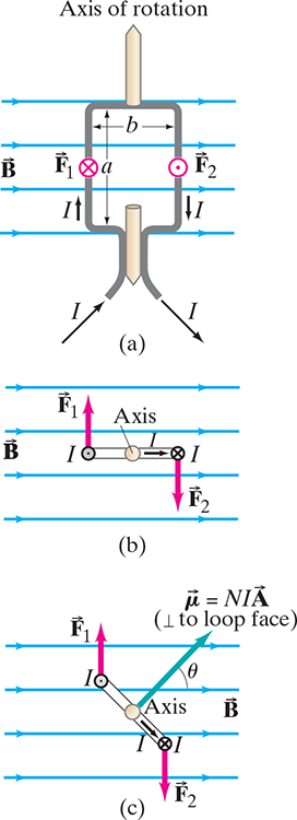
Calculating the torque on a current loop in a magnetic field .$\vec B$
(a) Loop face parallel to .$\vec B$ field lines; (b) top view; (c) loop makes an angle to .$\vec B$, reducing the torque since the lever arm is reduced. The vector .$\vec \mu$ is the “magnetic moment”.
When an electric current flows in a closed wire loop that’s in an external magnetic field, the magnetic force on the current can produce a torque
$$\tau = I aB \frac{b}{2} + I aB \frac{b}{2}$$
$$\dots = IabB$$
.$A = ab$ is the area of the loop
.$B$ is scalar of the magnetic field
Notice, the vertical (orthogonal) sections of wire experience no force from the magnetic field
If we have a coil of .$N$ loops of wire, the current is then .$NI$ so torque becomes
$$\tau = NIAB$$
We call .$\vec \mu = NI \vec A$ the magnetic dipole moment
The direction of .$\vec A$ (and thus .$\vec \mu$) is defined as perpendicular to the plane of the coil
We can then re-write our torque eq as
$$\vec \tau = NI \vec A \times \vec B$$
$$\dots \vec \tau = \vec \mu \times \vec B$$
Dipoles have some potential energy, found by
$$U = \int \tau d\theta = \int NIAB\sin\theta d \theta$$
$$\dots = -\mu B \cos\theta = - \vec \mu \cdot \vec B$$
 (a) Visualizing magnetic field lines around a bar magnet, using iron filings and compass needles. The red end of the bar magnet is its north pole. The N pole of a nearby compass needle points away from the north pole of the magnet. (b) Diagram of magnetic field lines for a bar magnet.
The Earth acts like a huge magnet. But its magnetic poles are not at the geographic poles (on the Earth’s rotation axis).
 $$dF_\vec{B} = dq (\vec v \times \vec B) = dq\bigg(\frac{d\vec l}{dt}\times \vec B\bigg) = I (d\vec l \times \vec B)$$
$$\dots\ \vec F = I (\vec l \times \vec B) = I l b \sin\theta$$
$$dF_\vec{B} = dq (\vec v \times \vec B) = dq\bigg(\frac{d\vec l}{dt}\times \vec B\bigg) = I (d\vec l \times \vec B)$$
$$\dots\ \vec F = I (\vec l \times \vec B) = I l b \sin\theta$$Force exerted by a uniform magnetic field on a moving charged particle (in this case, an electron) produces a circular path.