So far in the class, we have seen a wide range of additive and subtractive processes which are capable of creating components in metals, alloys, polymeric materials, ceramics, and composites. The one thing that these processes all have in common is that they are serial — meaning that one feature is produced after another in a predefined sequence. This serial nature inherently limits productivity and may require considerable operator skill. High operator skill, which leads to high overhead costs, is especially needed when a tool such as a lathe is manually operated, but may be needed even if the tool is computer numerically controlled, because work still has to be properly mounted and the machine correctly aligned to it. Subtractive processes have been used for centuries, both in the mass-production of precision components, and in one-off custom and prototyping jobs. Additive manufacturing has until recently been seen as a purely prototyping tool, although increasingly is being adopted for short-to-medium production runs.
Casting, and injection molding, on the other hand, form all features in a component almost simultaneously by forcing molten material into a mold, and potentially offer a faster, more affordable route to mass production. Injection molding is suitable only for mass production because of the high expense of the molds needed, and production runs of >10,000 are usually needed for economic operation. Casting comes in many flavors, from high pressure die-casting — which is really the equivalent of injection molding for processing metals — to gravity-driven sand-casting, which is used both for long production runs and for one-off fabrication jobs because of its ability to create very large components (> 1 m in some cases) with reasonable simplicity. The higher throughput of casting comes at the expense of lower achievable tolerances than machining (considerable fractions of a millimeter, as opposed to tolerances of a few micrometers). Forming processes such as casting are thus often followed by subtractive secondary processing to bring key features within tolerance. In this module we will highlight some of the attributes of casting and injection molding.
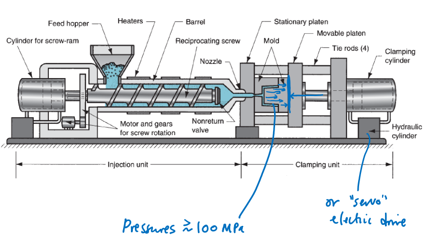
An injection molding machine consists of a mechanism to melt and extrude the polymer, and a molding unit. Injection molding is the workhorse of plastics manufacturing and can achieve cycle times of under a minute. Most plastics that are injection molded are thermoplastics, meaning that they can be reversibly changed between solid and fluid states by heating and cooling. Injection molding, however, can also be used to inject materials that covalently crosslink when heated (thermosetting plastics), making components that are more heat-resistant than thermoplastics. Injection molding has even been adapted to mold metal powders which are then sintered inside the mold (powder injection molding).
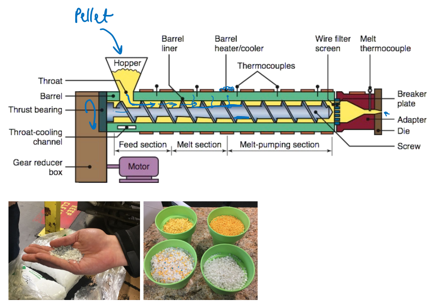
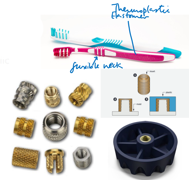
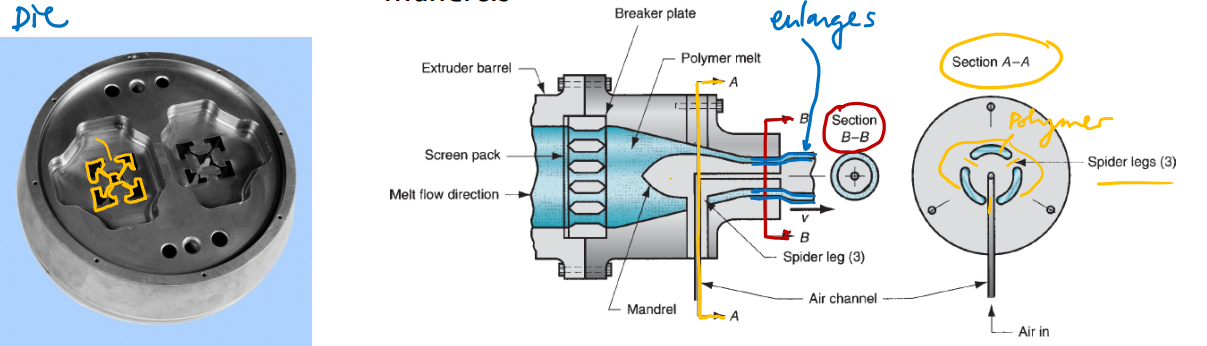
In conventional injection molding, the material to be molded enters the machine as solid pellets, which are drawn into a rotating, heated screw whose diameter decreases along its length to compress the material, drive out air voids, and turn it into a continuous molten flow. This flow is then extruded from a nozzle into a clamped mold, which is typically machined from tool steel but may contain inserts of other materials for specific applications.
Very thick material (viscosity) isn’t an issue due to large pressures used (Pressures typ. > 100 MPa)
Pellets go into hopper where they’re carried along and melted
The inside diameter of the screw gets larger so the pellets get compressed as they’re pushed along the screw until all air is driven out and it’s a constant stream
Wire mesh ensures only ’liquid’ passes (removes any debris/dust/funky filament)
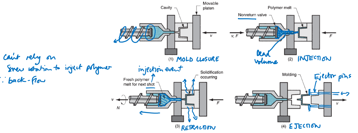
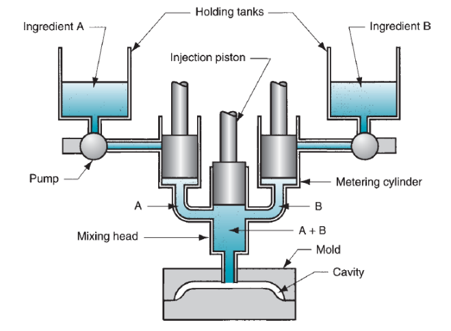
Heat up and screw the molten plastic to the tip of the core
Plunge the core into the mold and inject the molten material
Hold for a few seconds to let the material to solidify
Retract the core and bring back the mold to release the new piece
Cycle times approx. 10 s to 1 minute
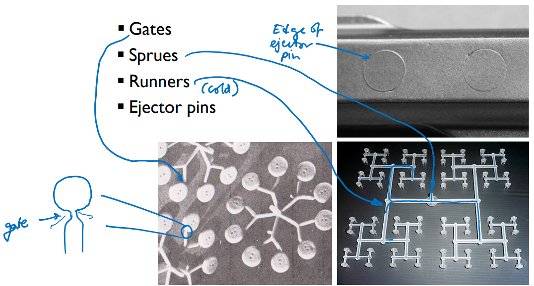
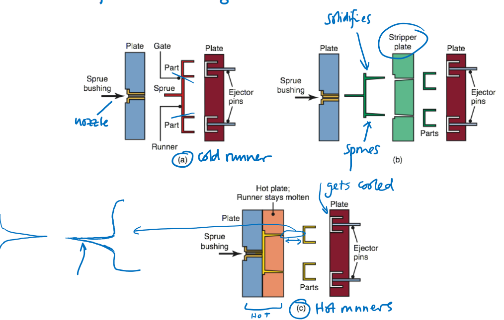
The mold is held at a temperature that is high enough to allow the polymer to fill the mold before solidifying, but cool enough that cycle time is not excessively long. The molded material needs to fall to below its glass transition temperature, below which the material becomes rigid, before it is ejected from the mold. Ejection is usually automated, with mechanical ejector pins emerging from the mold to push the molded component into a collection bin.
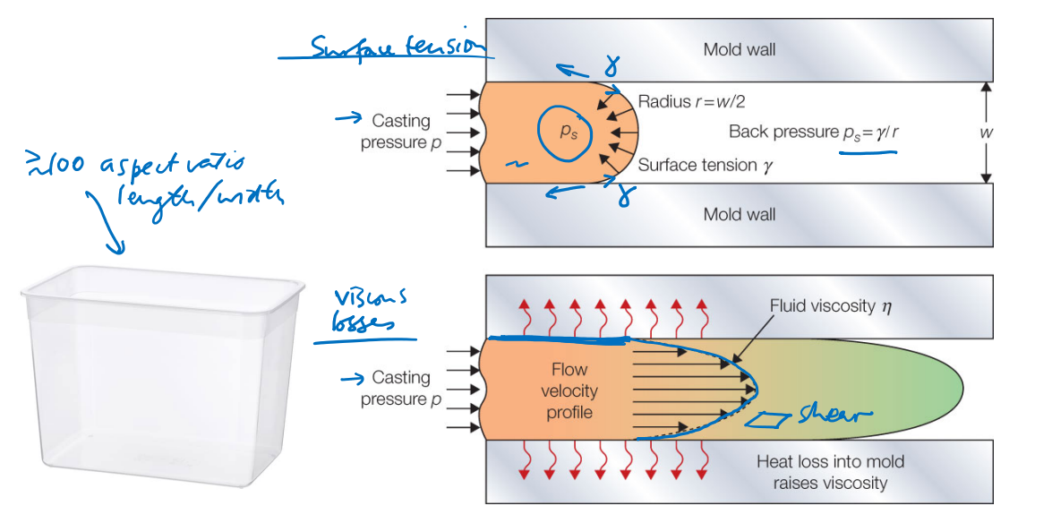
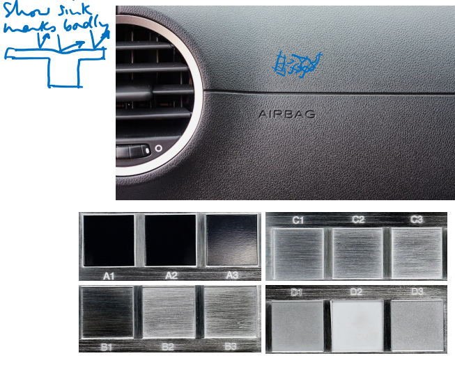
As soon as coming in contact with surface, the polymer looses heat
Thus, penetration depth is limited by how quickly the polymer ‘freezes’
You can increase pressure and temperature (thus viscosity) to circumvent this – but there are of course tradeoffs (longer heat up time, ‘maximum heat’ material can withstand)
For very tiny surface the surface geometry starts to matter too (e.x. income-angle may matter, as does mold material and how it interacts with the polymer)
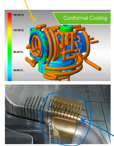
Materials with very high thermal conductivity e.g. Cu-Be alloys
For large moldings where achieving rapid enough cooling of the component is a challenge, high-thermal-conductivity materials such as copper–beryllium alloys may be used for part of the mold.
Material shrinkage needs to be compensated for in the sizing of the mold
Examples of typical linear contractions between solidification and room temperature:
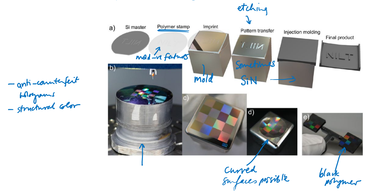
Nanopatterned hard mold coatings such as chromium nitride have recently been introduced to enable injection molding of nanostructures giving butterfly winglike structural color –
structural color
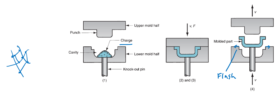
A lower-throughput but simpler and more affordable polymer molding technique is compression molding, in which a charge of the material to be formed is placed directly into the mold, and the mold halves are then brought together. The simplicity of the technique lends it to modest-sized production runs, and it is particularly suitable for thermosetting polymers, which crosslink when heated and can be removed from the mold at the molding temperature, because they do not need to be brought below a glass transition to acquire rigidity
Much simpler apparatus; tens of MPa (rather than hundreds)
Relies on a thermosetting material to solidify part
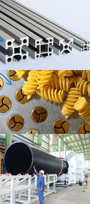
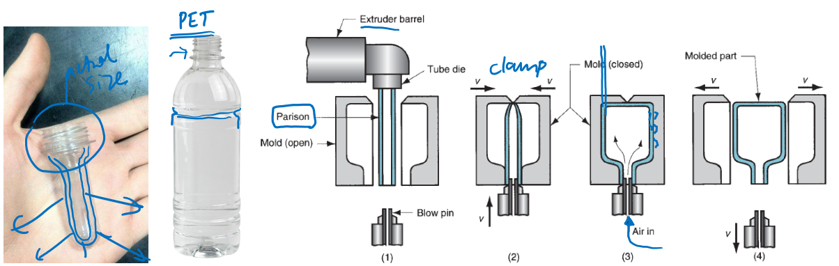
Blow molding is very widely used to produce components with thin side walls, such as plastic bottles. An extruded tube of softened thermoplastic polymer is clamped between two halves of a mold and air pressure inside the tube is increased. This expands the material until it conforms to the mold, stretching the material and making it thinner as it does so.
Better than injection molding for very thin walls
Extrusion followed by inflation
Or, can use injection molded preform (e.x. plastic bottle threading)
Forming of metals and alloys (Casting processes)
#
You have an established component design which needs to be mass-produced: casting can create many parts in less time than machining or additive manufacturing.
Geometric versatility: with appropriate mold design, sophisticated re-entrant geometries can be produced in about the same time as a simple geometry. Processing time does not increase strongly with geometric complexity, as it does in machining.
The need to process high-melting-point (“refractory”) alloys: melting point is correlated with hardness, making machining increasingly difficult as melting temperature increases. A highprecision casting technique such as investment casting can be a good option for achieving demanding tolerances with refractory alloys.
A desire to minimize material wastage: in casting, very little material is used beyond that required for the actual component, and any surplus (e.g. for risers and runners, as discussed below) can be re-melted and re-used. In contrast, in subtractive manufacturing much of the stock may be machined away as chips which are laborious and may be somewhat energy-intensive to recycle.
Heat loss and shrinkage is a concern, so extra risers are included (which also serve as vents)
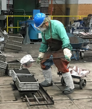
Manual process that creates large objects
Few-hundred runs a year, takes a few hours per run
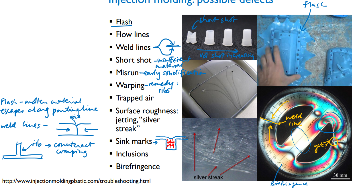
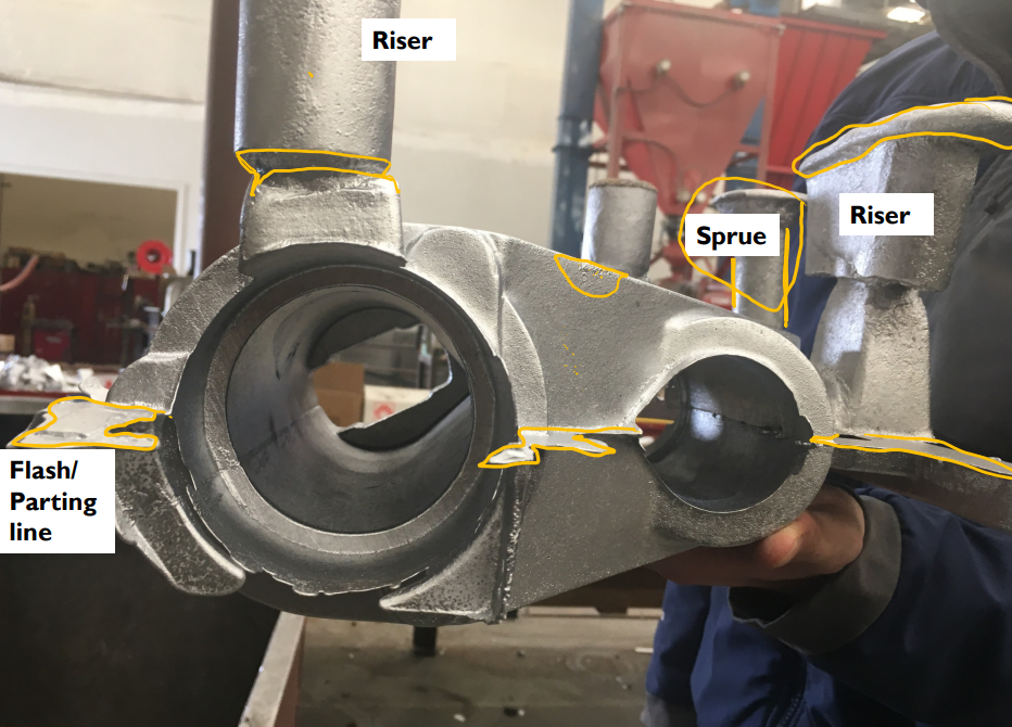
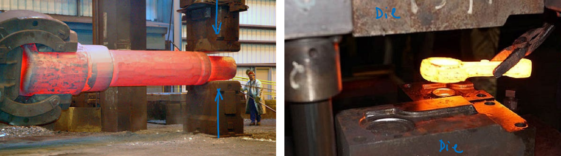
If the mold halves do not mate perfectly, molten metal may travel along their interface, leading to flash, which is usually thin enough to be easily broken off or abraded/machined away
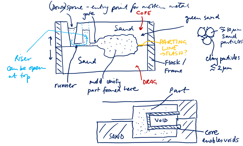
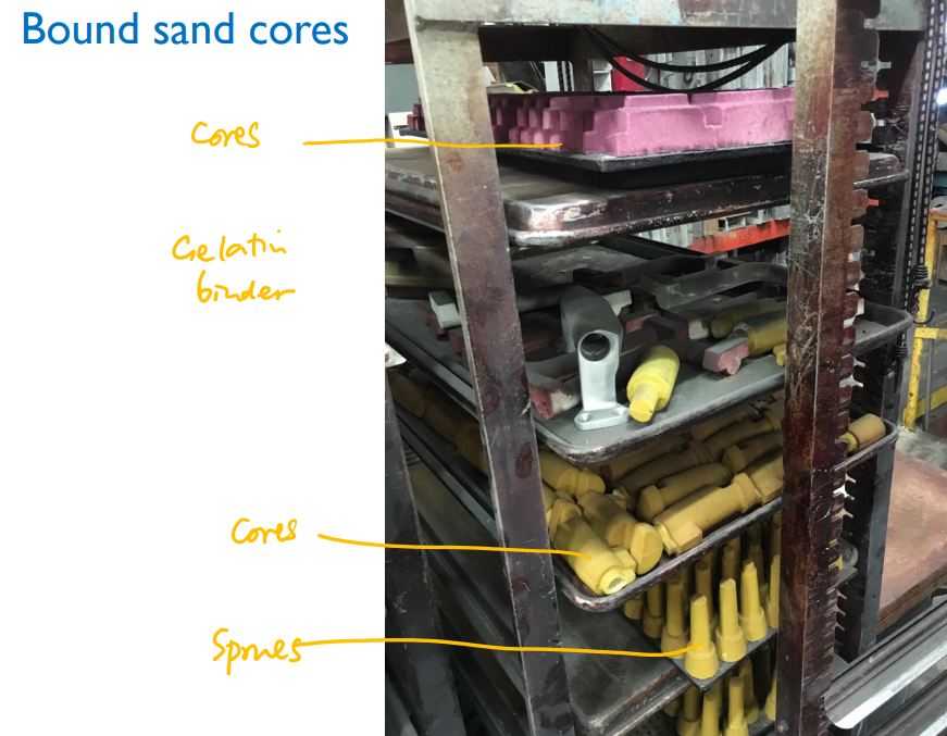
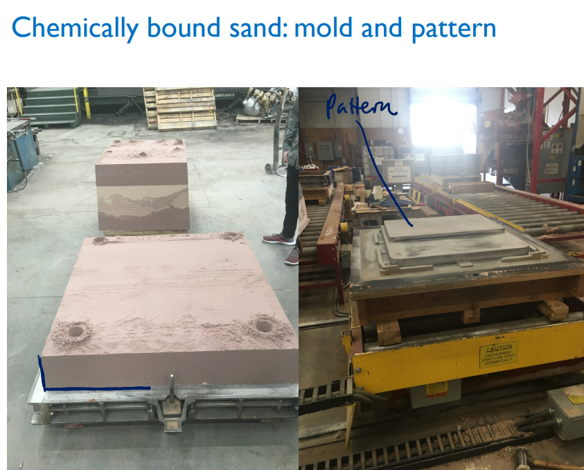
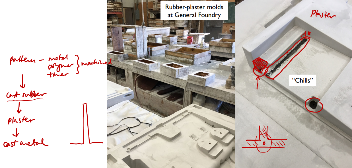
In sand casting, a single-use mold is produced by compacting a sand mixture around a pattern, which has the same shape as the final required component. The pattern might be made by machining timber or metal, or by additive manufacturing. The mold is prepared in two halves, the cope (top) and drag (bottom), with the sand being contained within a metal flask that has two interlocking parts. The pattern is removed from the compacted sand mixture before the mold is closed up. If re-entrant or hollow components are to be cast, one or more cores are introduced into the mold before the cope and drag are brought together. These cores are also single-use and may be made from sand that is bound with organic material such as gelatin.
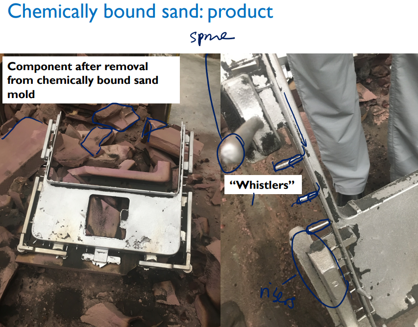
The mold needs to have several features in addition to the cavity that will contain the actual cast component. First we need a downsprue, or sprue, into which the molten metal can be poured. Second we need runners which are horizontal channels that carry the molten metal from the sprue to the mold cavity.
Thirdly we need one or more risers, which allow air to escape from the mold as the metal enters, and are also designed to be the last part of the metal to solidify. Risers can thus provide a small amount of surplus material to compensate for the volume shrinkage that occurs when the metal solidifies. Risers need to be strategically positioned around the mold cavity to supply this material where it is needed. The design of sprues, runners and risers requires skill and experience, and is one of the key competitive advantages of successful foundries.
Sand, or silica, is used as a mold material because of its high melting point (~1600 ˚C) relative to that of the material being cast (e.g. 660 ˚C for aluminum). Sand on its own, however, will not hold the shape of the mold. Green sand is a sand, clay, and water mixture which holds together via the capillary forces between particles and by particle jamming between the larger sand particles and the much smaller clay particles. Green sand has the advantage that it can simply be shaken off the cast component after solidification, and recycled many times.
If a mold cavity has particularly large unsupported regions, a stronger mold material may be needed. In this case the clay and water may be replaced by a stronger binder, which may thermally or chemically cure to make a solid mold material. Such molds are more robust but are not reusable.
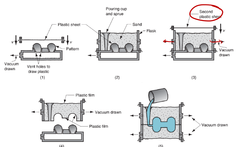
An alternative approach is to use loose sand and compact it under vacuum between plastic sheets to make it solid. The plastic is vaporized as soon as the molten metal hits it.
Options for sand-based molds:
Green sand
Typically SiO2, particles a ≥ 10µm in diameter
Mixed with 7-10% clay (e.g. kaolinite, 2SiO2.Al2O3.2H2O). Typically < 2 µm diameter
Bound with 2-4% water
Clay particles promote mechanical jamming of sand particles and with the water bind sand together
Shake off and sieve to re-use
Dry or chemically bound sand
Mix sand with an organic binder
May require heat to cure: 200 − 320 ℃
Or may cure via a chemical reaction
Enables larger unsupported mold cavities than green sand
But sand harder to re-use: needs grinding down
Why use sand?
It is refractory: i.e. high melting point – higher than the metal/alloy being poured.
e.g. silica: melts at 1600 ℃; pure aluminum: melts at 660 ℃
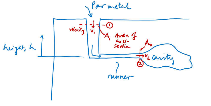
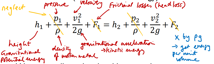
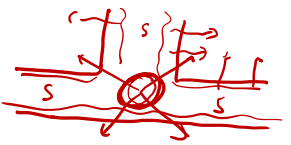
As molten metal is poured by hand from the crucible in which it has been heated, it accelerates under gravity and flows into the mold cavity. The height of the sprue is crucial in determining the speed with which the metal enters the cavity, and hence how long it takes to fill. If filling is insufficiently fast, there is a risk that metal will solidify before filling is complete; if, however, it is too fast, the momentum of the molten metal may dislodge sand from the walls of the mold, leading to the inclusion of sand impurities in the cast component and weakening the casting.
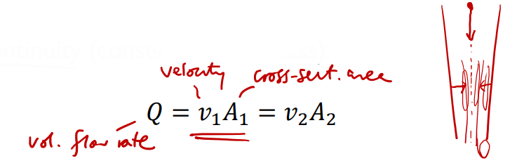
The speed can be estimated by considering the amount of gravitational potential energy that is converted to kinetic energy during the pouring process. The other important concept here is continuity, where we assume that the molten metal is incompressible (constant volume). So molten metal will flow at a higher velocity along narrower parts of a runner, for example.
Continuity of mass and energy together explain why the downsprue is sometimes tapered: to prevent a pressure drop and aspiration of air (or sand) from the sidewalls into the molten metal.
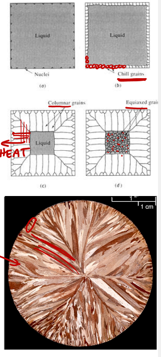
Solidification occurs when sufficient heat has been conducted out of the metal into the surrounding mold (or from the top of a sprue or riser to the air). The outside of the component will usually solidify earliest because of its proximity to the sand, leading smaller grains or crystals of metal to form near the surface of the component and larger, columnar grains to be directed radially towards the center of the component. This inhomogeneous grain structure may give undesirable mechanical properties which may need to be corrected by subsequent heat treatment or by machining back the surface.
A widely used model for solification time is Chvorinov’s Rule, in which the solidification time is expressed as the product of a mold constant, .$C_M$, and a geometrical term, .$(V/A)^2$. The mold constant is a purely material-dependent constant depending on the properties of the alloy being cast and the mold material. The geometrical term is the square of the .$V$olume to surface .$A$rea ratio of the component being cast. The reason the exponent is taken to equal 2 is that most of the heat leaves the cast material by conduction (rather than convection or radiation), so heat is transported by diffusion. The relevant timescale thus increases as the square of the relevant linear dimension for heat transport.
Total solidification time .$T_{TS}$ is composed of the sum of:
.$n \approx 2$: heat transport from molten metal is largely by conduction; so is governed by diffusion of atomic vibrations – consider
Fick’s laws of diffusion
Solidification begins from the outside of the mold cavity
Small “chill crystals” form (which can be machined away)
Two types of shrinkage are relevant in casting. The first is solidification shrinkage, which is a volumetric reduction associated with the phase change from liquid (amorphous) to solid (ordered, crystalline). A good question to ask about solidification shrinkage is whether the material is effectively solid or liquid while this shrinkage is happening, as its state during shrinkage will determine the shape of a component after the shrinkage occurs. To answer this question, we can envision the liquid-to-solid phase change happening through the nucleation and growth of solid metal crystals within the cooling molten metal. Thus, up until the moment when solidification is complete, we can reasonably think of the material as still being fluid, so that gravity will cause it to fill the walls of whatever container it is in. Thus, solidification shrinkage will not be uniform in all directions, but rather will predominantly be in the vertical direction (see the shrinkage question in the homework on casting).
The second form of shrinkage is thermal contraction, a type of shrinkage that you have probably already encountered in other contexts. Here, the solid cast component reduces in dimensions linearly with temperature, as its temperature falls from the melting point down to the temperature at which it is extracted from the mold.
Cast components exhibit shrinkage:
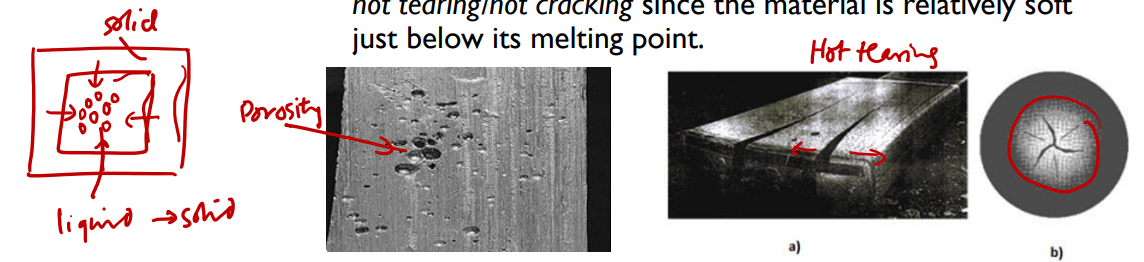
Solidification shrinkage (due to liquid-to-solid phase change: disordered liquid becomes a denser, more ordered lattice structure). May lead to unwanted porosity if additional molten metal cannot enter the region vacated by the shrinking metal.
Thermal contraction (reduction in solid volume as component cools from melting point to room temperature). May lead to hot tearing/hot cracking since the material is relatively soft just below its melting point.
Small voids in casting; caused by solidification shrinkage .$^1$
Appropriately placed risers to supply material during solidification; chills
Misrun
Metal solidifies before reaching the extremities of the mold cavity
Avoid high-aspect-ratio features in design; pour metal at higher temperature; use heated mold (e.g. cast iron); redesign sprue/runner/gate and/or add additional sprue locations
Hot cracking/tearing
Differential thermal contraction of solidified material: material which has just solidified, but is still soft because of its high
Chills to promote faster cooling of thicker sections so molten regions are not trapped inside the casting
Pin holes
Air entrapped in molten metal flow
More careful pouring; appropriate sprue design
Flash
Metal escapes along parting line between two mold halves
More careful packing of sand; post-processing of casting to remove flash
Cold shut
Metal flows through multiple paths in mold and solidifies before the metal from the different paths meets
Same remedies as for misrun
Cold shot
Splattered, solidified metal entrained in flow
Slower pouring
Sand wash
Erosion of mold surface in metal flow
Reduce pouring velocity/height
Sand blow
Embedded sand particles in casting
Careful design of sprue taper
.$^1$: Voids can appear in the more massive regions of a casting which solidify later than the surrounding material, or the surface of a casting sinks, producing aVdefect known as a pipe. Some of the effects of solidification shrinkage can be counteracted by introducing chills, which are more thermally massive and conductive regions of a mold, made, e.g., of steel and embedded in the mold in close proximity to the more massive regions of a cast component to accelerate cooling.
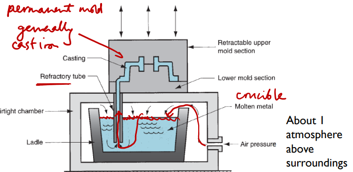
Rather than pouring the molten metal directly into the mold, it is held in a ladle beneath the mold, and pneumatic pressure is used to drive the metal through a tube into the mold. This has the advantage that it can be automated, so that filling time can be made highly repeatable. It also helps to prevent the oxides that form at the surface of the molten metal from being injected to the mold — in gravity casting, some of these oxides risk entering the mold during pouring and weakening the cast component. The mold in low-pressure casting is typically metallic (e.g. cast iron) and reusable.
Advantages over sand casting:
Metal enters cavity at a more controlled velocity
Mold is reusable: better surface finish
Molten metal is taken from center of the bath – scum (oxides) from surface does not enter the mold
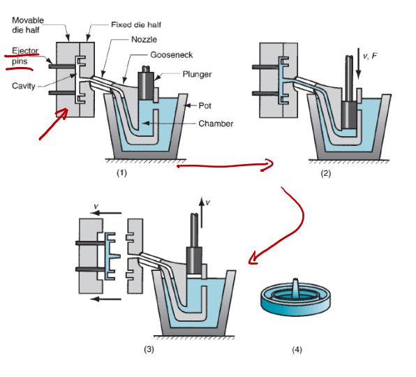
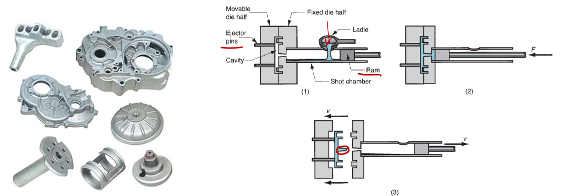
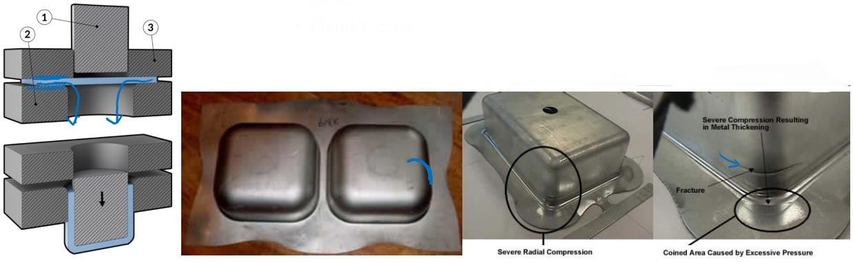
Die casting comes in two main types: hot chamber and cold chamber. The choice of machine design depends on the melting point of the metal to be cast, with the hot chamber approach more suited to lower-melting-point materials for which it is feasible to build a plunger assembly that can be immersed in the molten material. The pressures in die casting range from several MPa to over 100 MPa, which is comparable with plastic injection molding and enables molten metal to be driven rapidly into the fine geometries in a mold. Casting dies are made of alloys with higher melting points than the metal to be injected, and require highly precise machining.
Suitable for metals with higher melting points (e.g. Al and alloys, brass, Mg alloys) since plunger mechanism is not immersed in the melt
Pressures around 14-140 MPa are needed because the molten metal cools more rapidly
These high pressures can cause flash
Not as fast as hot-chamber die casting because of the ladling process
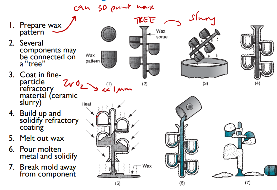
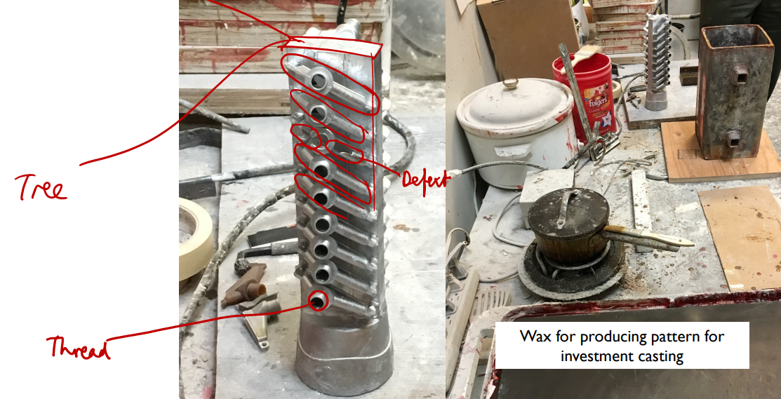
Involves coating a single-use wax pattern with a slurry which is a suspension of ceramic particles in liquid. The slurry is baked to solidify it, the pattern is melted out, the metal cast and the mold then broken off after solidification. The pattern can be produced to extremely fine tolerances (e.g. by 3D printing or machining), and the slurry particles are far finer than sand particles, so the surface finish achievable in this way is far superior to that of sand casting.
Prepare wax pattern
Several components may be connected on a “tree”
Coat in fine-particle refractory material (ceramic slurry)