That is, changing .$\vec B$, not .$\vec B$ itself, induces current
Constant magnetic fields produce no current in a conductor
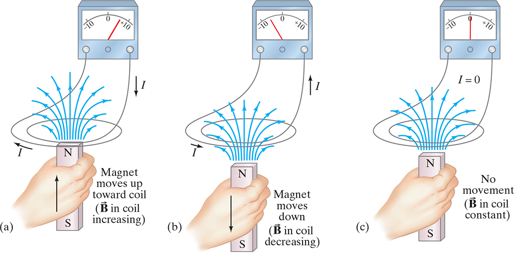
This process is called electromagnetic induction
It doesn’t matter if the magnet or coil moves, only that there is relative motion between the two
(a) A current is induced when a magnet is moved toward a coil, momentarily increasing the magnetic field through the coil. (b) The induced current is opposite when the magnet is moved away from the coil (.$\vec B$ decreases). In (c), no current is induced if the magnet does not move relative to the coil. It is the relative motion that counts here: the magnet can be held steady and the coil moved, which also induces an emf.
EMF is proportional to the rate of change of the magnetic flux .$\Phi_B$ passing through the circuit or loop with area .$A$
Given a uniform magnetic field .$\vec B$ we write
$$\Phi_B = B_\perp A = BA \cos\theta = \vec B \cdot \vec A$$
For non-uniform fields, we need to integrate:
$$\Phi_B = \int \vec B \cdot d \vec A$$
The unit of magnetic flux is the tesla-meter, called the weber: .$\text{1 Wb = 1 T$\cdot$ m$^2$}$
Faraday’s law of induction
The emf .$\mathscr{E}$ induced in a circuit is equal to the rate of change of magnetic flux through the circuit:
$$\mathscr{E} = -N\frac{d\Phi_B}{dt}$$
.$N$ is the number of loops closely wrapped so the flux passes through each
Lenz’s Law
A current produced by an induced emf creates a magnetic field that opposes the original change in magnetic flux
Faraday’s law is negative accordingly
Realize that we know have to magnetic fields:
The changing magnetic field or flux that induces the current, and
The magnetic field produced by the induced current (all currents produce a magnetic field) which opposes the charge in the first
Note: The magnetic field created by induced current opposes change in external flux, not necessarily opposing the external field
It is important to note that an emf is induced whenever there is a change in flux through the coil – this can be done in three ways:
Changing the magnetic field
Changing the area .$A$ of the loop in the field
Changing the loop’s orientation .$\theta$ wrt the field
Lenz’s law is used to determine the direction of the (conventional) electric current induced in a loop due to a change in magnetic flux inside the loop. (The loop may already be carrying its own ordinary current.) To produce an induced current you need (1) a closed conducting loop, and (2) an external magnetic flux through the loop that is changing in time.
Determine whether the magnetic flux .$\Phi_B = \vec B \cdot \vec A$ inside the loop is decreasing, increasing, or unchanged.
The magnetic field due to the induced current: (a) points in the same direction as the external field if the flux is decreasing; (b) points in the opposite direction from the external field if the flux is increasing; or (c) is zero if the flux is not changing.
Once you know the direction of the induced magnetic field, use the right hand rule to find the direction of the induced current that would give this induced .$\vec B$
Always keep in mind that there are two magnetic fields: (1) an external field whose flux must be changing if it is to induce an electric current, and (2) a magnetic field produced by the induced current.
If a wire is already carrying an electric current, the total current while the magnetic field is changing will be the algebraic sum of the original current and the induced current.
If a conductor begins to move in a magnetic field, an emf is induced
We can use Faraday’s law and kinematics to derive an equation:
$$\mathscr{E} = \frac{d\Phi_B}{dt} = \frac{B dA}{dt} = \frac{B (l\cdot v\ dt)}{dt} = Blv$$
.$v$ is the speed of the conductor
.$dA = l\ dx = lv\ dt$ is the change in area over time .$t$
Be careful! This is a generalization where .$B, l, v$ are mutually perpendicular
If they aren’t, we use the component of each that are mutually perpendicular
An emf induced on a conductor moving ina magnetic field is sometimes called a motional emf
We could also derive this using our force eq from ch27:
$$\vec F = q\vec v \times \vec B$$
When the conductor moves with .$v$, as do its electrons
Since .$\vec \perp \vec B$, each electron feels force .$F = qvB$
The direction determined by the right hand rule (red)
If the rod is not in contact with the conductor, electrons would collect at the upper end leaving the lower positive
Therefore, there must be an induced emf!
If the rod is in contact with the conductor, the electrons will flow into the conductor and there will be a clockwise current in the loop
To calculate emf, we determine the work .$W$ needed to move a charge .$q$ from one end of the rod to the other against this potential difference:
$$W = F \times d = (qvB) \times (l)$$
$$\mathscr{E} = W/q = qvBl/q = Blv$$
(a) A conducting rod is moved to the right on the smooth surface of a U-shaped conductor in a uniform magnetic field .$\vec B$ that points out of the page. The induced current is clockwise. (b) Force on an electron in the metal rod (moving to the right) is upward due to .$\vec B$ pointing out of the page. Hence electrons can collect at the top of the rod, leaving .$+$ charge at the bottom.
Electric generators produce electricity by transforming mechanical energy into electric energy
Also called dynamos
Opposite of what a motor does
Consists of many wires wound around an armature that can rotate in a magnetic field
This axel is turned by mechanical means (belt, steam, water falling, etc.) and an emf is induced in the rotating coil
An ac current is thus the output of a generator
An ac generator
Each brush is fixed and presses against a continuous slip ring that rotates with the armature
If the armature is rotating clockwise; then, .$\vec F = q \vec v \times \vec B$ applied to a charged particles in the wire
Lenz’s law tells us that the (conventional) current in the wire .$b$ on the armature is outwards, towards us, thus, the current is outwards, through brush .$b$
After one-half revolution, wire .$b$ will be where .$a$ is now and the current at .$b$ will be inwards. Thus, the current produced is alternating!
If the loop is made to rotate in a uniform field .$\vec B$ with constant angular velocity .$\omega$, the emf produced is
$$\mathscr{E} = - \frac{d\Phi_B}{dt} = - \frac{d}{dt}\int \vec B \cdot d \vec A = -\frac{d}{dt}\big[BA\cos\theta\big]$$
.$A$ is the area of the loop
.$\theta$ is the angle between .$\vec B$ and .$\vec A$
Since .$\omega = d\theta/dt \Longrightarrow \theta = \theta_0 + \omega t$, we choose .$\theta_0 = 0$ so
$$\mathscr{E} = - N BA \frac{d}{dt}(\cos(\omega t)) = N BA \omega \sin (\omega t)$$
.$N$ is the number of loops in the rotating coil, assumed to be .$1$ unless stated otherwise
Transformer: Device used to increase or decrease an ac voltage
Made up of two coils know as the primary and secondary coil
Primary is the input, secondary is the output
These can be interwoven (with insulated wire); or can be linked by an iron core that’s laminated
We assume energy losses (in resistance and hysteresis) can be ignored
When an ac voltage is applied to the primary coil, the changing magnetic field it produces will induce an ac voltage of the same .$f$requency in the secondary coil
However, secondary voltage, .$V_S$, changes according to the number of turns or loops in each coil:
$$V_S = N_S \frac{d\Phi_B}{dt}$$
.$N_S$ is the number of turns in the secondary coil
.$\Phi_B/dt$ is the rate at which the magnetic flux changes through each coil
The input voltage, .$V_P$, is related to this rate too:
$$V_P = N_P \frac{d\Phi_B}{dt}$$
.$N_P$ is the number of turns in the primary coil
This follows because the changing flux produce a back emf, .$N_P\ d\Phi_B / dt$, in the primary that exactly balances the applied voltage .$V_P$
This is because of Kirchhoff’s rules
This is only the case if the resistance of the primary can be ignored (which we assume)
Then, we can divide these two equations, assuming little or no flux loss, to find
$$\frac{V_S}{V_P} = \frac{N_S}{N_P}$$
.$V_S$ and .$V_P$ can be the rms or peak values for both
$$ \mathscr{E} = \oint \vec E \cdot d \vec l = - \frac{d\Phi_B}{dt}$$
The first two terms come from the fact that the emf .$\mathscr{E}$ induced in a circuit is equal to the work done per unit charge by the electric field
This is then combined with the relation of a changing magnetic flux to the the field it produces
Forces Due to Changing .$\vec B$ are non-conservative
#
Electric field lines produced by a changing magnetic field are continuous; they form closed loops
That is, while a conservative force (such as a electrostatic magnetic field) integrated over a line integral is zero .$\big(\oint \vec E_\text{electrostatic} \cdot d \vec l = 0\big)$, the electric field created by an magnetic field is not zero: .$\oint \vec E_\text{non-static} \cdot d \vec l = - \frac{d\Phi_B}{dt}$
This implies that forces due to changing magnetic fields are non-conservative and we can’t define a potential energy (or even a potential function!) at a given point in space
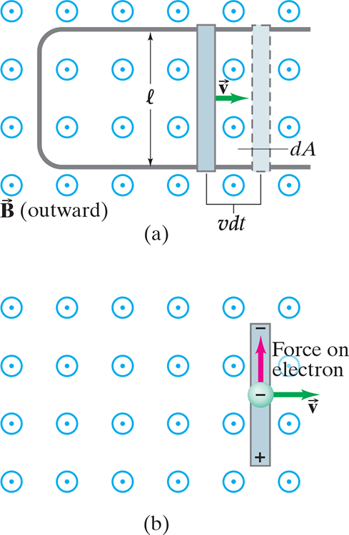 (a) A conducting rod is moved to the right on the smooth surface of a U-shaped conductor in a uniform magnetic field .$\vec B$ that points out of the page. The induced current is clockwise. (b) Force on an electron in the metal rod (moving to the right) is upward due to .$\vec B$ pointing out of the page. Hence electrons can collect at the top of the rod, leaving .$+$ charge at the bottom.
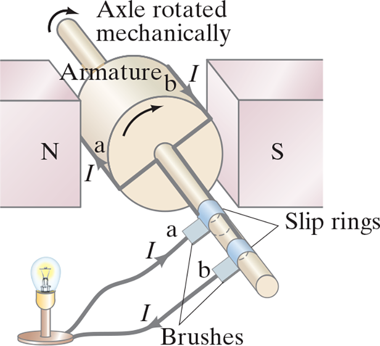
(a) A dc generator with one set of commutators, and (b) a dc generator with many sets of commutators and windings.