Orthographic projections #
Formal (working) drawings: purpose #
- Need a formal way of documenting designs
- Legal documents i.e patents; contracts may rely on them
- Must stand on their own – readable to any human
- No subsequent explanation
- No verbal assists
- No ambiguity
- Solution: multi-view
orthographic projection
- World-wide engineering standard
- Can easily include tolerances

What is a projection? #
Projection of a 3D object’s edge onto a 2D plane by rays perpendicular to that plane such that they are parallel to one another (unlike real-world)
Dashed lines represent hidden detials
Projections are independent of projection distance
Projection depends on part orientation #
- Use judgement to select most useful/informative orientation
- Often, a projection is clearest when a significant flat surface of the object is parallel to the projection plane
- Left is a better pictorial view (it’s more 3D)
- Right is better because it’s face is parallel

Multi-view orthographic projection #
- Usually can’t convey all information about an object using a single projection
- Use multiple projections from different viewpoints
What is an orthographic projection? #
- Orthos: Greek for “right”, “true”, or “correct”
- Each projection is formed by rays perpendicular (at right angles) to its projection plane
- The different views of a multi-view drawing are taken from viewpoints at right angles to each other
- Multi-view orthographic projection is a standardized, accepted form of representing objects
- Graphos: drawing
“Glass-box” interpretation #
- Need an agreed way to organize different projections on the page
- Imagine projecting object onto sides of a box
- Unfold the box onto the page
- So-called “third-angle” projection
- Will not necessarily show all six projections
- Projections are aligned

Example of multi-view orthographic projection #
- Lines connecting a given point in adjacent views are always perpendicular to the “unfolding” line (of the “glass box”)


View interpretation #
- Need to consider how many views needed to remove ambiguity

Multiview characteristics #
- Inclined face
- Face in 2 views
- Line in 3rd view

- Oblique face
- Face in 3 views

- Face in 3 views
Which is the oblique face? #

How many views? #
- Example: cut from sheet material
- Unlikely to be multiple levels of relief
- Projections of edges therefore unnecessary
- Grooves or etched patterns would be labeled as such

In this case, two views not enough to describe geometry completely – we need 3
- Thick enough material that there could conceivably be multiple levels of relief: side view needed
- In this particular example, all features pass through the full thickness of the material

Would any two views be enough to describe the geometry completely?
Example of hidden lines #

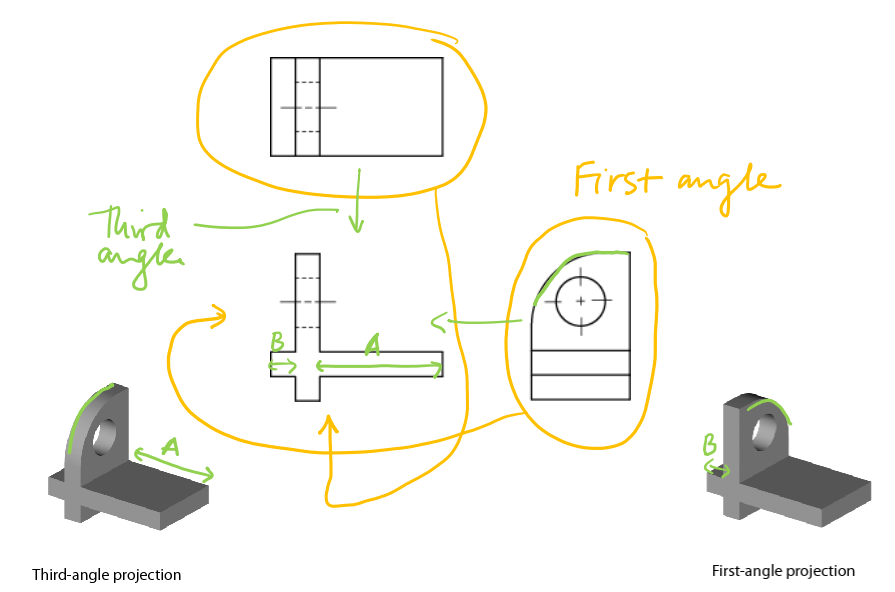
First- vs third-angle orthographic projection #
- 3rd angle projection used in U.S.
- glass box convention

- 1st angle projection (Europe, Japan, India)
- top/bottom and left/right arrangement reversed

- top/bottom and left/right arrangement reversed
Example of why specifying 1st or 3rd angle matters
ANSI standards (Y14.5) #
- Adopted by drafters and engineers to expedite the transfer of information
- Maximum information with the minimum drawing
- Will only cover highlights here
- Views
- At least two views (except flat sheet)
- Add views as required so the dimensions of the object can be defined entirely in true length measurements
- Add views as necessary for presentation clarity
- Solid lines
- Assumed to be intersections of planes or optical limits of cylinders
- Tangent edges are usually not shown, or shown using phantom lines
- Hidden lines
- Use to add information, clarity (good practice not to over-use)
- Use views requiring the fewest hidden lines
- Center lines
- Use to mark the centers of holes, or cylindrical surfaces ≥180º
- Circles
- Assumed to be intersections of cylinders and orthogonal planes
- Section views
- Used for clarification of internal geometries
- Explained in a later lecture

Small cuts on curved surfaces
Small radii, intersections of blended planar surfaces shown as a line
Representing threads use schematic representations
Parts with odd rotational symmetry Simplify to a symmetrical view even though that is not a strictly accurate projection
Tangent and non-tangent surfaces
- A line drawn where a curved surface meets a planar surface indicates no tangency: i.e. there is an abrupt change in the angle of the surface
- No drawn line indicates tangency: i.e.surface angle is continuous/smooth


Pictorial views #
Review of isometric, oblique, and perspective #


Color; shading #


Section views #


Advanced projections #


Auxiliary views #


Additional notation #
Dimensioning #


Showing welds #


