30.1 Mutual Inductance #
- When two wires are near one another, they induce an emf in one another
- This emf is proportional to the rate of change of the flux passing through it
- The flux passing through the coil is generated by the other coil’s current
- If the two coils are held in place then the total flux is proportional to the mutual inductance
$$M = \frac{N_2 \Phi_{21}}{I_1}$$
- .$\Phi_{21}$ is the total flux passing through coil 2 (induced by the current in coil 1, .$I_1$)
- .$M$ depends on “geometric” factors such as the size, shape, number of turns, and relative positions of the two coils, and whether a ferromagnetic material is present
- The SI unit for mutual inductance is the Henry; .$\text{1 H = 1 V$\cdot$s/A = 1$\Omega \cdot$s}$
A changing current in one coil will induce a current in the second coil.
- The emf induced in coil 2 due to a change in current 1 can be written now as $$\mathscr{E_2} = -N_2 \frac{d\Phi_{21}}{dt} = -M \frac{dI_1}{dt}$$
30.2 Self-Inductance; Inductors #
- This concept also applies to isolated coils too
- When a changing current passes through a coil (or solenoid), a changing magnetic flux is produced inside the coil, and this in turn induces an emf in that same coil. This induced emf opposes the change in flux (Lenz’s law).
- If the current through the coil is increasing, the increasing magnetic flux induces an emf that opposes the original current and tends to retard its increase.
- If the current is decreasing in the coil, the decreasing flux induces an emf in the same direction as the current, thus tending to maintain the original current.
- If this inductance (coil) is in a circuit, it thus can provide a source of emf, in addition to any battery present or other sources of emf.
- When a changing current passes through a coil (or solenoid), a changing magnetic flux is produced inside the coil, and this in turn induces an emf in that same coil. This induced emf opposes the change in flux (Lenz’s law).
- Self-inductance .$L$ and the emf it induces is given by
$$L = \frac{N\Phi_B}{I}$$
$$\mathscr{E} = -N \frac{d\Phi_B}{dt} = -L \frac{dI}{dt}$$
- An ac circuit always contains some inductance, but often it is quite small unless the circuit contains a coil of many loops or turns. A coil that has significant self-inductance .$L$ is called an inductor
- Inductance can serve a useful purpose in certain circuits, but it’s often just a nuisance in a circuit.
- If inductance is large, the change in the current will be small, and therefore the current itself if it is ac will be small.
- The greater the inductance, the less the ac current.
- An inductance thus acts something like a “resistance” to impede the flow of alternating current.
Solenoid Self-Inductance #
- The magnetic field of a solenoid is .$B = \mu_0 nI$ where .$n = N/l$
- Thus, the flux is .$\Phi_B = BA = \mu_0 NIA/l$ so we can derive $$L = \frac{N \Phi_B}{I} = \frac{\mu_0 N^2 A}{l}$$
30.3 Energy Stored in a Magnetic Field #
- When an inductor with inductance .$L$ is carrying current .$I$ which is changing at the rate .$dI/dt$, energy is being supplied to the inductor at the rate $$P = I \mathscr{E} = LI \frac{dI}{dt}$$
- Thus, the work needed to increase the current in an inductor from zero to some .$I$ is
$$W = \int P dt = \int_0^I LI\ dI = \frac{1}{2}LI^2$$
- This is also the (potential) energy stored in a conductor when it is carrying current .$I$
- Just as the energy stored in a capacitor can be considered to reside in the electric field between its plates, so the energy in an inductor can be considered to be stored in its magnetic field.
- E.x. the energy stored in a solenoid is $$U = \frac{1}{2}LI^2 = \frac{1}{2} \bigg( \frac{\mu_0 N^2 A}{l} \bigg)\bigg( \frac{Bl}{\mu_0 N}\bigg)^2 = \frac{1}{2} \frac{B^2}{\mu_0}Al$$
- We can think of this energy as residing in the volume enclosed by the windings; .$Al$
- Then the energy density (energy per unit volume) is
$$u = \text{energy density} = \frac{1}{2}\frac{B^2}{\mu_0}$$
- This equation is analogous to that for an electric field, .$ \frac{1}{2}ϵE^2$
30.4 LR Circuits #
(a) LR circuit; (b) growth of current when connected to battery.
- At the instant the switch connecting the battery is closed, the current starts to flow.
- It is opposed by the induced emf in the inductor because of the changing current. As soon as current starts to flow, there is also a voltage drop across the resistance; .$V = IR$
- Hence, the voltage drop across the inductance is reduced and the current increases less rapidly as it approaches .$I_0 = V_0 / R$ as seen in (b)
- The emfs in the circuit are the battery voltage .$V_0$ and the emf .$\mathscr{E} = -L (dI/dt)$ in the inductor (which opposes the current)
- Hence, we can find sum of potential charges around the loop where .$I$ is the current at any instance by using the loop rule: $$V_0 - IR - L \frac{dI}{dt} = 0 \Longrightarrow L \frac{dI}{dt} + RI = V_0$$
- We can integrate the later term from .$t = 0, I = 0$ to a later time .$t$ when current is .$I$:
$$\int_0^I \frac{dI}{V_0 - IR} = \int_0^t \frac{1}{L}dt \Longrightarrow - \frac{1}{R} \ln \bigg( \frac{V_0 - IR}{V_0} \bigg) \frac{t}{L}$$
$$\dots \Longrightarrow \frac{V_0 - IR}{V_0} = e^{- \frac{Rt}{L}} \Longrightarrow I = \frac{V_0}{R}(1-e^{-t/\tau})$$
- .$\tau = \frac{L}{R}$ is the time constant: the time required for the current .$I$ to reach 63% of it’s maximum value .$V_0/R$
- When the battery is removed from the circuit…
- Voltage .$V_0$ becomes zero, so .$L \frac{dI}{dt} + RI = 0$
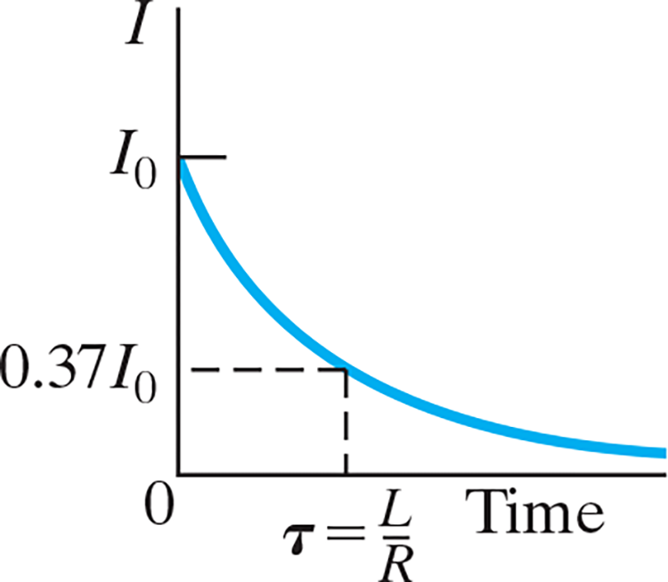
- We can integrate this and solve for .$I$ $$\int_{I_0}^I \frac{dI}{I} = - \int_0^t \frac{R}{L} dt$$ $$\dots \Longrightarrow I = I_0 e^{-t/\tau}$$ - .$\tau = L/R$ is the time it takes current to decrease to 37% of it’s initial
30.5 LC Circuits and Electromagnetic Oscillations #
- Any electric circuit can contain the three basic components: resistance, capacitance, and inductance, in addition to a source of emf.
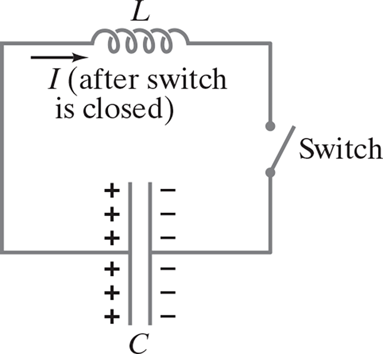
- Suppose the adjacent circuit is initially charged so one plate has charge .$Q_0$ and the other .$-Q_0$ and that the potential difference is .$V = Q/C$
- At .$t = 0$ the capacitor immediately begins to discharge. As it does so, the current .$I$ through the inductor increases. We now apply Kirchhoff’s loop rule (sum of potential changes around a loop is zero): $$-L \frac{dI}{dt} + \frac{Q}{C} = 0$$
- Because charge leaves the positive plate on the capacitor to produce the current .$I = dQ/dt$ so we can rewrite the equation as
$$\dots \Longrightarrow \frac{d^2 Q}{dt^2} + \frac{Q}{LC} = 0 \Longrightarrow Q = Q_0 \cos(\omega t + \phi)$$
- .$Q_0$ and .$\phi$ are constants that depend on the initial conditions
- .$\omega t + \phi$ is in radians.
- Because we have .$\phi$, the amplitude isn’t .$Q_0$ unless .$\phi = 0$
- .$\omega = 2\pi f = \sqrt{ \frac{1}{LC} }$
- We can then plug in our sinusoidal equation to find a function for .$I$: $$I = -\frac{dQ}{dt} = \omega Q_0 \sin(\omega t + \phi)$$ $$\dots \Longrightarrow I_0 \sin(\omega t + \phi)$$
- Energy stored in capacitor: $$U_E = \frac{1}{2}\frac{Q^2}{C} = \frac{Q_0^2}{2C}\cos^2(\omega t + \phi)$$
- Energy stored in magnetic field: $$U_B = \frac{1}{2}LI^2 = \frac{Q_0^2}{2C}\sin^2(\omega t + \phi)$$
- Total energy stored: $$U = U_B + U_E = \frac{Q_0^2}{2C}$$
Period: .$T = \frac{1}{f} = \frac{2\pi}{\omega} = 2\pi \sqrt{LC}$