Processes based on light-sensitive liquids #
Stereolithography (SLA) #
- Also called Digital Light Printing (DLP)
- Thermoforming molds are most commonly made with stereolithography, i.e orthodontic aligners
- Used because the molds need complete geometric customizability
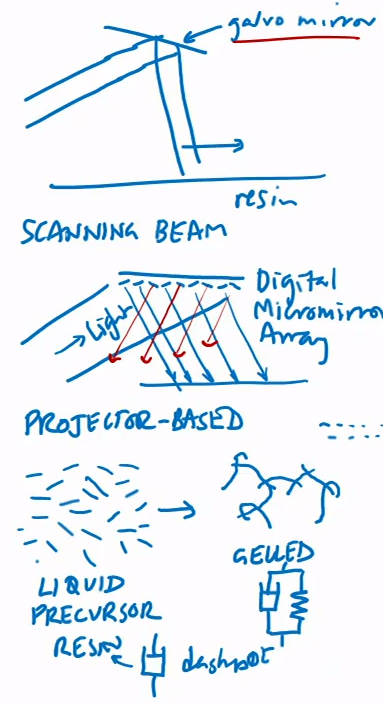
- A tray, bath or vat of a photo-sensitive liquid (a resin) is locally crosslinked (solidified) with a scanning laser beam or projected light pattern (i.e Photoinitiator), usually violet (~405 nm) or ultraviolet (~365 nm)
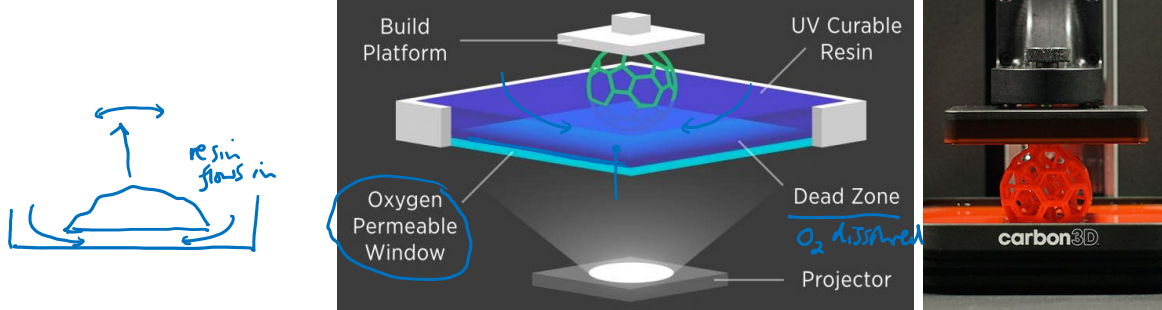
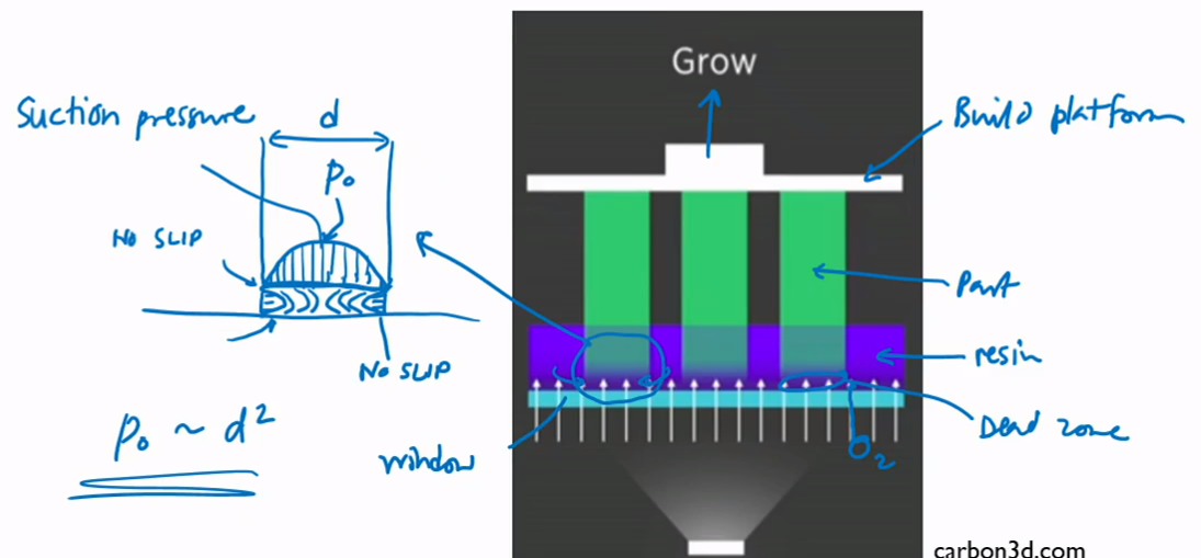
- Unwanted bonding can be avoided by making the base oxygen-permeable (e.g. by making it out of an elastomeric material, as in the Carbon 3D systems) since oxygen inhibits the photocrosslinking reaction and an oxygen-rich layer will form in the resin just above the permeable window because of air diffusing through the window
- Covalent bonds form between the molecules in the liquid, forming a solid material (this reaction is called photocrosslinking)
- Absorption of photons as they pass through the liquid limits crosslinking to a small layer (typically tens of μm thick) at a time
- Parts are more isotropic (versus FDM), have almost matte finish
- Two machine design approaches:
- Right: Light shines up through a window; part gradually drawn up out of a tray of resin
- Requires more liquid
- Projection Printing (below): Light shines down onto liquid surface; platform moves down into the vat as the part builds up
- Printed object drawn upwards out of tray of resin
- Separation from tray: peeling or O2-inhibited dead layer
- Right: Light shines up through a window; part gradually drawn up out of a tray of resin
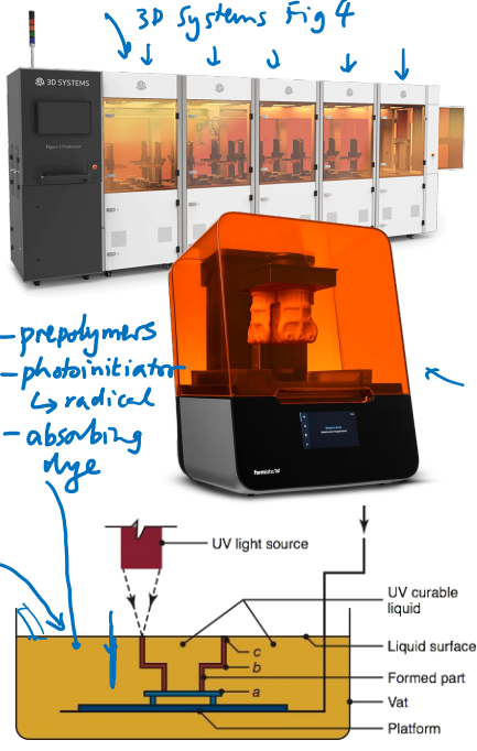
- In older SLA configurations, the platform is submerged in the resin, the illumination comes in from above the resin surface, and the platform moves down into the resin bath after each layer was printed. Sometimes a mechanical ‘wiper’ is used to distribute a thin, uniform layer of uncured resin on top of the component before the next exposure step
- In new designs, the illumination is shone through a window in the bottom of the resin tray, and the platform moves upwards, pulling the object out of the tray as it prints.
- This approach has the advantage of requiring a less deep resin tray, and eliminating the need for a wiper, but means that the machine designer must ensure that the resin does not bond to the window at the base of the resin tray.
Resin solidification in stereolithography #
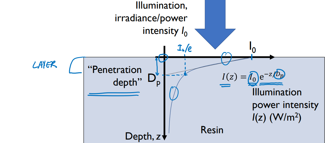
- Beer-Lambert model: Absorption of the illuminating light means that exposure dose .$E(z)$ (measured in W/m.$^2$) of the light is at its highest at the point where the light enters the resin, and decreases exponentially with depth below resin surface .$z$:
$$E(z) = E_0 e^{-z/D_p}$$
- This curve (a property of the dye/resin) follows a first-order
exponential decay
- This is common across most materials that absorb light; for each unit traveled by the photon, there’s a finite probability of getting absorbed.
- E.x. 10% of photos are absorbed in the first 10 microns, 10% of the remaining photons in the next 10 microns, etc.
- This curve (a property of the dye/resin) follows a first-order
exponential decay
- A newer, potentially faster, approach for processes that rely on photocrosslinking is to expose each 2D layer in one single exposure step, rather than scanning a beam of light. The digital micromirror devices that are an integral component of modern video projectors can be used to pattern the photocrosslinking wavelength of light. Even with this layer-by-layer approach, there is still a need to
- Whether 3D printing will always involve this slicing approach is an open question. Since slicing often imparts anisotropic mechanical properties to printed components and limits their layer-to-layer strength, there may be a strong case for developing full 3D control over the material deposition process, so that, for example, the deposition head would move in the x, y and z directions simultaneously. Path planning to avoid collision between the machine and the component would be a significant challenge slice a 3D object into multiple 2D images.
- .$D_p$ is the penetration depth, a resin property
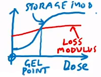
- The resin at a particular location will photocrosslink when the total illumination dose exceeds a critical value called the curing dose
- The depth into the resin at which the curing dose is reached is termed the curing depth
- .$E$ is the dose: the time integral of power intensity over the layer time
- Measured in J/m.$^2$
- In projector-based systems, the source is .$E_0 = I_0\ t_\text{layer}$
- .$I_0$ is the illumination irradiance/power intensity, which is proportional to the energy of the incoming particles per area W/m.$^2$
- In laser-scanning systems, .$E_0$ is a function of illumination power intensity (W/m.$^2$), beam diameter w (m), and scanning speed, v (m/s):
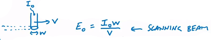
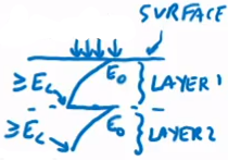
- Gelation just occurs at the curing depth, .$D_c$ where the resin receives the curing dose, .$E_c$: $$E_c = E_0 e^{-D_c/D_p} \Longrightarrow D_c = D_p \ln \bigg( \frac{E_0}{E_c} \bigg)$$
- Cured material may not be very strong at curing depth, so layers typically overlap in .$z$ direction to ensure material is all well-gelled
- Thermal and light curing are done to finish these surfaces
Hydrodynamic stresses in dead zone #
- This is the central rate-limiter in stereolithography
- Suction pressure forms around bottom of part
- Proportional to the square of the part width
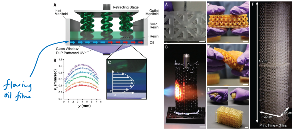
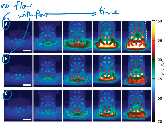
Thermal management for high print speeds #
- Oil cools down print, enables meters per hours printing
SLA vs FDM #
| Type | Pros | Cons |
|---|---|---|
| SLA | Can reduce layer thickness to much smaller levels than FDM (see especially the Carbon 3D system which claims sub-micrometer layer thicknesses) | Only a single resin material can be patterned per object |
| Can use digital micromirror devices to print an entire layer in one flash – potentially higher throughput than FDM | Mechanical properties of photocrosslinkable resins lag behind those of FDM filaments | |
| With thinner layers, can get more isotropic mechanical strength than in layered FDM | ||
| FDM | Very wide range of printable filament materials now available, with specialist mechanical, thermal, optical, and electrical properties | Anisotropic mechanical strength because of layered deposition – weaker layer-to-layer than within layers |
| Apparatus can be very affordable (a few hundred dollars in some cases) | Surface roughness comparable to extruded filament diameter – cannot directly print shiny surfaces |
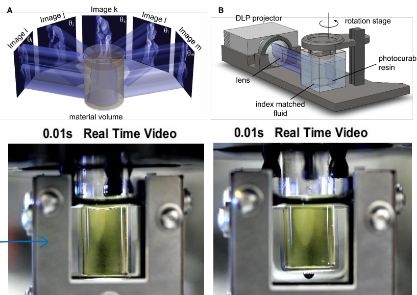
Computed Axial Lithography #
- CAL: Developed at Cal!
- A layer-free tomographic approach to photopatterning involving synthesis of 3D light dose
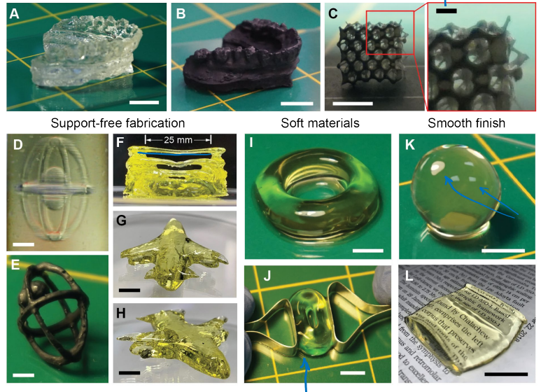
- Benefits: higher speed, the ability to print into more viscous materials, and the ability to avoid the use of solid supporting structures for delicate geometries.
- Enables a wider range of resin materials (notably higher viscosity resins)
- There a discrete number of layers, but then end up being ‘smeared’ so they are relatively smooth
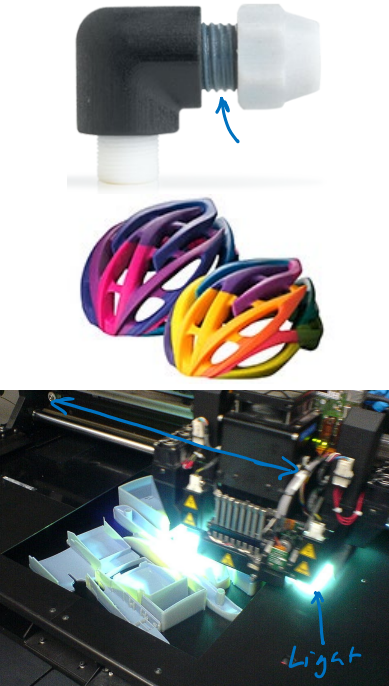
Poly Jet printing #
- Also called ink-jet printing
- Used when a high degree of material heterogeneity is needed in a single object (e.g. in color, or mechanical stiffness)
- These have been commercialized, for example, by the company Stratasys with the brand name “PolyJet”
- Inkjet-dispensed polymer inks are built up layer by layer and photocured (crosslinked). Layers down to ~16.$\mu$ thick.
- Elastic modulus and color can be varied spatially by mixing inks
- A wide range of mechanical properties (including elastomers) are now possible
- Rigid glassy polymers to soft rubber-like performance possible
- Note that these are “simulated” materials: the printed inks are photocured whereas the final production material may be, e.g., thermoplastic
- Typical machines can carry about five different material cartridges at a given time, and can tune material properties by depositing finely interspersed patterns of droplets of these materials.
- Far more expensive than FDM or basic SLA tools.
- Electrically conductive materials are beginning to emerge
- Available in Jacobs Hall:
- Objet260 Connex3
- Objet350 Connex3
- Interchangeable ink cartridges
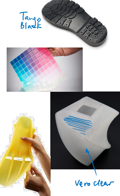
- Soft, rubbery, tacky:
- Tango range
- ~ few MPa Young’s Modulus
- Rigid:
- Vero (white, black, yellow, magenta, cyan, clear available)
- Digital ABS
- ~ few GPaYoung’s Modulus
- Soluble support:
- FullCure705
- Remove by hand, water or NaOH solution
Powder/binder methods #
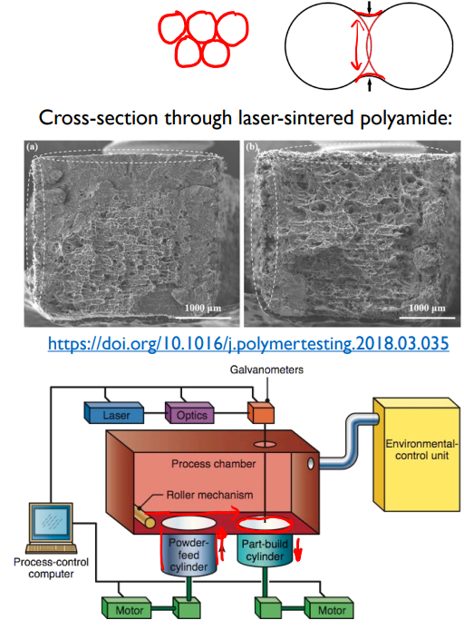
Selective laser Sintering (SLS) #
- Use a heat source (usually a scanning laser beam) to sinter powders of the structural material directly, without a binder
- Can be applied to thermoplastic polymers (esp. Nylon), metals, and even ceramics
- A thin layer of the powder is rolled across the printing bed, and then a laser is scanned across the layer, delivering enough heat that the powder particles melt only at their surfaces.
- Atoms or molecules at the contacting interfaces between particles diffuse faster in the elevated temperature and cause adjacent particles to connect to each other.
- Powder particles are heated enough that surfaces melt– atoms/molecules at their surfaces interdiffuse, bonding the particles.
- Because the powder is not fully melted, parts usually retain some porosity
- Can weaken the component compared to continuous bulk material
- The pores can serve as stress concentrators and promote crack propagation across the component
- The surface finish can be rough — the roughness is comparable to the metal particle size
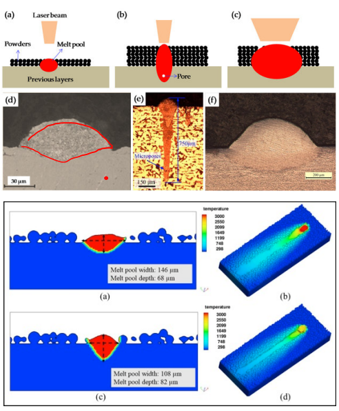
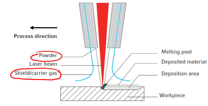
Selective Laser Melting (SLM) #
- Also called Direct Metal Laser or Directed Energy Deposition
- Laser (infrared light) actually melts the powder
- Removes porosity by melting the particles
- Thermal gradients can be a problem
- Computer generators now account for thees gradients and deformations
- Changes pattern order and energy distribution
- There has been a move away from metal SLS towards complete melting of the metal powder that is being fused.
- Greater control of grain structure and lower porosity than with selective laser sintering
- Fully dense structures achievable
- Scanning laser beam completely melts the powder during processing
- No binders being employed but rather the structure of the component being built up directly from metal.
- These processes may be layer-by-layer or, increasingly commonly, via a direct spray
- Isn’t feasibly monetarily right now
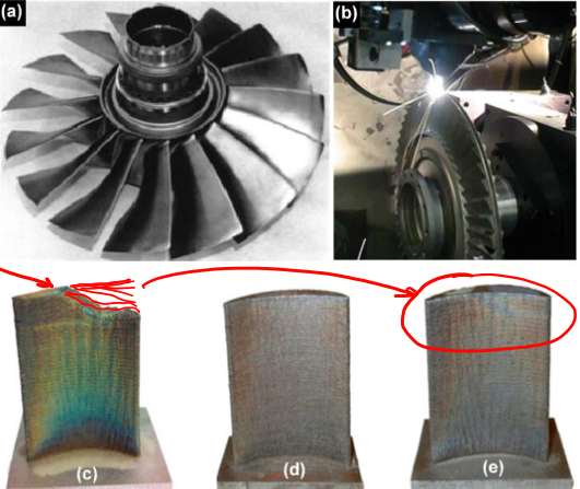
Examples of components #
- 3D printed gas turbine blades
- Polycrystalline nickel superalloy
- Layer by layer powder fusion
- Survived 13,000 rpm at 1250 °C
- Application: pressure sensor housing in General Electric jet engine compressor
- Made using SLM
- Co-Cr alloy
- 19 of them in the GE LEAP engine
- Replaces a casting process
- Development time up to a year faster than using casting
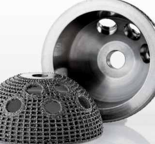
- Example of remanufacturing with SLM
- Used when material is very expensive and not recyclable/reusable
- Used when material is very expensive and not recyclable/reusable
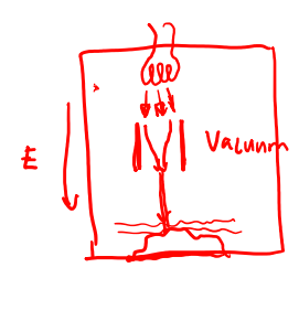
Electron-beam melting #
- Like SLM, produces fully dense parts
- Operates in vacuum to avoid metal oxidation and so that the electrons can follow a straight path without colliding with air molecules.
- In contrast, SLM uses an inert gas atmosphere
- Vacuum allows higher temperatures to be used (> 800 K)
- Reduces oxidation and porosity due to adsorbed gases
- Materials more limited than SLM
- Examples: Ti grade 2, Ti6Al4V, Inconel 718, CoCrMo
- Features down to a few micrometers are possible although printing times are slow compared with SLS or even SLM
Hybrid subtractive/additive manufacturing #
- In the last few years hybrid machines have been demonstrated that combine a subtractive machining center (lathe, mill) with an additive capability
- The idea is to start with the smallest possible piece of stock material, deposit additional features of a component (e.g. flanges) additively on to that stock, and then machine back to the final shape, benefiting from the higher precision and surface finish of turning and milling.
- A machine made by DMG-Mori is now on the market and uses a metal spray together with a laser to deposit material, rather than a powder bed approach.
Powder-binder method #
One approach to printing objects from powders (which may include metal, polymer or ceramic powders) is to selectively dispense a binder (a sprayable ‘glue’, usually a polymer) on to layers of dry powder, holding the powder together in specific locations. After printing, the part is removed from the surrounding unbound loose powder. For polymeric parts, the binder can be colored and constitutes part of the final object. For metal or ceramic printing, the binder is subsequently be driven off (vaporized) with high heat after the whole part has been printed, and the powder is also sintered together by the heat (see below for explanation of sintering).
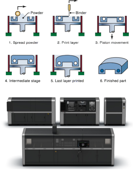
- Polymer powder and deposited binder (may be colored).
- Left: schematic illustration of the threedimensional-printing process. Source: After E. Sachs and M. Cima.
- Can also be applied to binders with metal powders, which are later sintered/fused (Desktop Metal, Markforged…)
Emerging methods #
- Directly fuse thermoplastic powders layer-by-layer
- Something like a 3D photocopier
Powdered materials #
Polymer powder production
- Ball milling: grind below glass transition
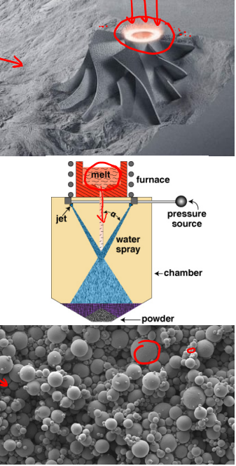
Metal powder production
- Solid-state reduction: crush ore, pass through furnace
- Atomization:rapidly freeze molten spray
- Electrolysis: deposition in powder form (e.g. Cu)
- Chemical, e.g. precipitation from solution
Size distributions typically Gaussian
- SLM: typical average ~ 30 microns
- The more spherical, the more easily it flows
- Some powders more porous
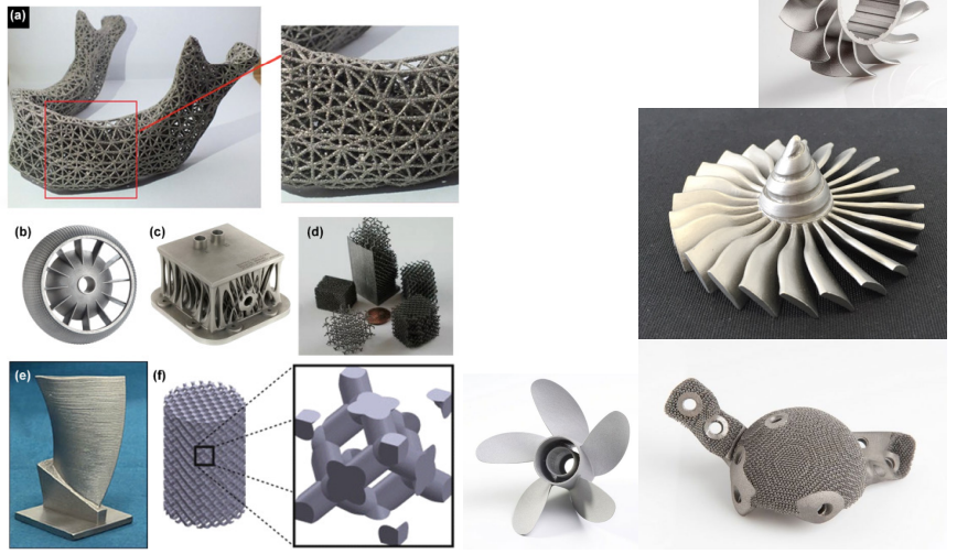
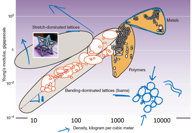
Design for additive manufacturing #
- Stretch-dominated lattices
- e.g. octet truss structure
- One of the stiffest structures known
- Produced, e.g., by projection microstereolithography
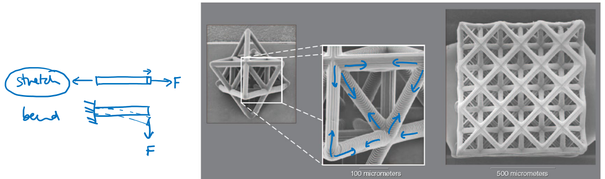
Tuning material properties with structure #
- Printed cellular structures can offer new classes of material
Current challenges with 3D printing #
- Speed – for a single material and non-freeform geometry, machining is still probably quicker; injection molding is certainly faster
- Lower mechanical strength – directionality, porosity, surface flaws
- Surface finish – roughness often of many microns
- Resolution – from ~ 0.25 mm for basic FDM down to a few microns for SLA/SLS/SLM. Sub-micrometer resolution possible for two-photon SLA.
- Expense of input material – fine filaments, powders, inks: some proprietary consumables
Potential future applications of 3D printing #
- Food?
- Clothes?
- Human organs?
- Houses?
- What are the challenges of 3D printing?
- Intellectual property; forgery
- Difficulty of regulating production (e.g. of weapons; organs)
- Carbon footprint (energy input) of 3D-printed components vs traditionally manufactured components
- Overall will 3D printing create or destroy jobs?