Abrasion – rough, abrasive wheels rotate at high speed across the surface of the component, removing particles of the workpiece. This approach is well suited even to the hardest of materials, although control of geometry is not as great as in cutting operations, for example.
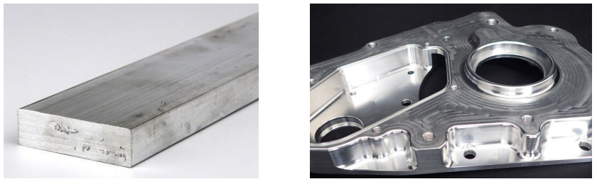
Stock materials tend to be readily available (and inexpensive compared with the specialist powders that are used in some additive processes such as selective laser melting
Precision and finish are exceptionally good – probably better than any other family of processes
Need strength / structure
Material cannot be molded (it’s the only feasible process)
Doesn’t alter heat treatment (if feed and speed isn’t too high)
Short runs – no specialized tooling costs
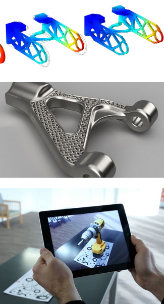
Easy customization & More control for iterative product development – every component produced can be different if needed
All you need is to generate new .gcode; versus a whole mold
Slow for large run sizes compared to forming processes
Most processes are “serial”, meaning that each feature on the component needs to be produced sequentially, making the processes slow. This is in contrast, for example, to molding/casting operations where the entire component is produced in approximately one step.
Fairly costly in comparison
Large amount of waste generated (low efficiency)
High operator skill is often demanded, raising processing costs
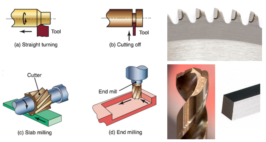
Cuts across metal grains – not as strong as forged or possibly cast components focus on material cutting Cutting operations rely on wedge-shaped teeth
To understand the key concepts of metal cutting, we focus specifically on lathe turning
i.e. a reduction in the diameter of a cylindrical component using a cutting tool.
We focus on the turning of metals and their alloys, although turning is also widely used to process polymeric materials and even composite materials (wood being one “composite” that is regularly turned).
Cutting operations rely on wedge-shaped teeth
Lectures 4 and 5 will focus on cutting-based operations; Lecture 6 will look at some of the others A close look at a metal cutting operation
The workpiece (or simply work — the solid material that is to be reduced in diameter) is held firmly at one end in a chuck, whose jaws are tightened against the workpiece enough that the friction between the work and the chuck is always enough to resist the torques experienced by the work during cutting.
The work is rotated, using an electric motor, at angular velocity .$\omega$, which is typically hundreds or even thousands of revolutions per minute. Let us call the axis of rotation z. If the radius of the workpiece is a at the location of cutting, then the linear, tangential velocity of the work relative to the tool is .$V_\text{cut} = \omega a$, provided that .$\omega$ is expressed in radians/second (to convert from rev/min to rad/sec multiply by .$2\pi/50$).
The cutting tool is mounted on a cross-slide/carriage assembly, which enables precise control of the cutting edge along the z axis and also radially outwards from the z axis (let us call this radial direction the x axis). The carriage and cross-slide could be moved by manual screws or by computer-controlled motors with positional feedback.
Once the work is rotating at its target speed, the tool is positioned slightly to the right of the end of the work and the tool is moved inwards in the x direction (towards the rotational z axis) by a distance .$d$, called the depth of cut. The tool is then moved from right to left along the workpiece at a velocity called the feed rate given by .$V_\text{feed} = f\omega$, where .$f$ is the feed, or the distance moved by the tool along the z axis in one revolution of the work.
Feed rate is a velocity, while feed is a distance per revolution — this subtlety of terminology is important to note. Note that in almost any turning process, .$V_\text{cut} » V_\text{feed}$
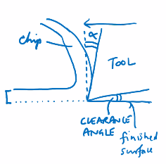
The metal that is cut, or shaved, away from the workpiece is called the chip, and depending on (1) how brittle or ductile the work material is, (2) the shape of the cutting tool, and (3) the speed of cutting, the chip may be either a fairly continuous spiral or a series of small chips that regularly fracture.
Many small chips are desirable from a practical perspective because, unlike very long continuous chips, they do not tend to become tangled around the work and potentially scratch it.
Cutting tools will often have protrusions on their front surface that are designed to break up a chip as it comes off the workpiece.
So in turning, a spiral of material is being removed from the work that has initial cross-section .$d \times f$ and with the tool sweeping through the material with velocity .$V$. Thus, the volumetric removal rate of material is .$R_\text{MR} = Vdf$.
More ductile materials (aluminum, mild steel, copper etc): long, spiral-shaped chips of material
More brittle materials (e.g. cast iron): comes off in short chips
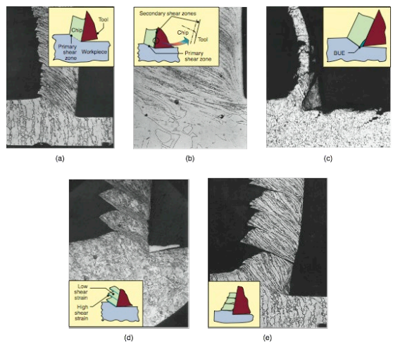
Basic types of chips produced in metal cutting and their micrographs: (a) continuous chip with narrow, straight primary shear zone; (b) secondary shear zone at the tool-chip interface; (c) continuous chip with built-up edge; (d) segmented or nonhomogeneous chip; and (e) discontinuous chip.


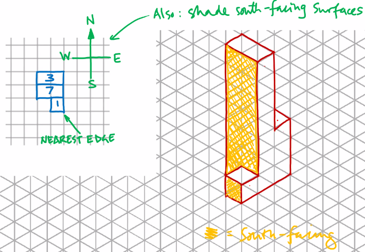
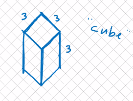 #
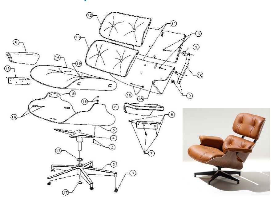
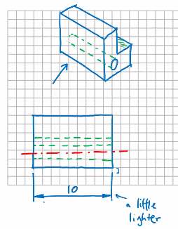
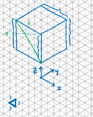
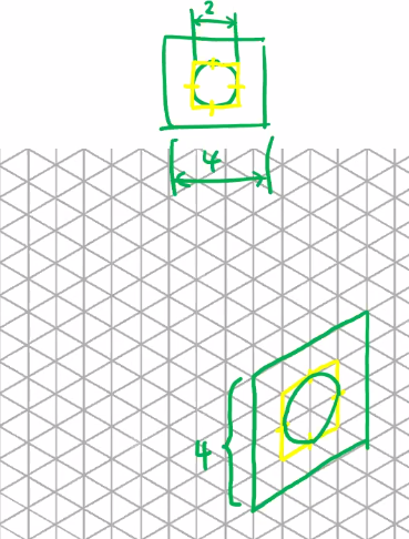
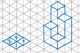
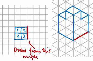
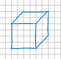
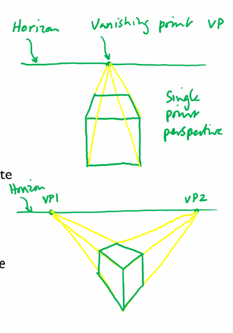
#Example of axonometric drawing


 Lectures 4 and 5 will focus on cutting-based operations; Lecture 6 will look at some of the others A close look at a metal cutting operation