Real manufactured objects deviate (even if slightly) from the ideal geometry
Surfaces not perfect planes
Axes not perfectly straight, etc
So, we need a procedure to interpret measurements from a component to establish a “best fit” for the datum plane or axis
Use a physical “datum simulator” like a rigid, flat surface (e.g. granite table) to rest against the component
Measure multiple points $(x,y,z)$ with
CMM or
optical metrology and fit the plane or axis datum in software (e.g. use least-squares regression – advanced software available for this)
The number of datums needed to define a given tolerance depends on the geometry of the component and the type of tolerance
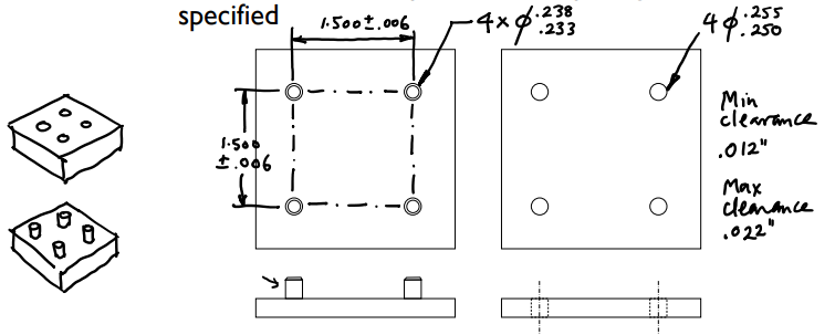
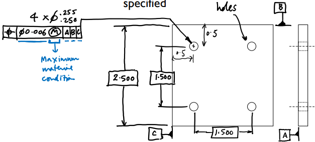
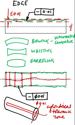
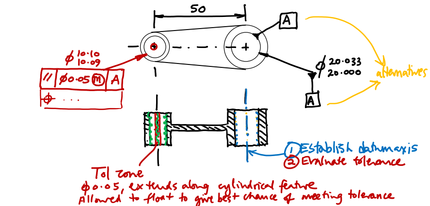
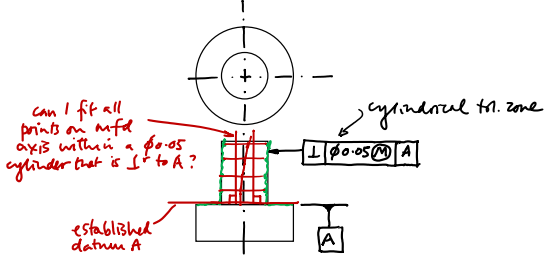
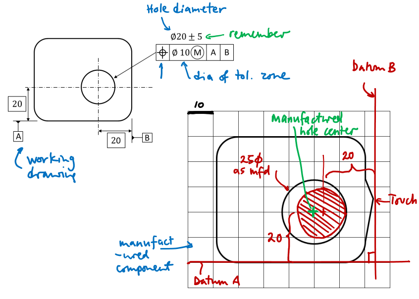
Cylindrical tolerance zone must fit inside this diameter
Needs diameter symbol, Ø
Compute axis position by forming an
equidistant set by
bisecting pairs of measured points on surface of the cylindrical feature
Matters because we are generally trying to mate one cylindrical feature with another
e.g. peg and hole
Note that a cylindrical feature can have a straight axis without having straight edges, as would be the case when a feature exhibits waisting or barreling.
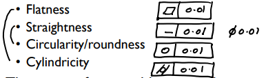
2D version of straightness – applies only to planar feature
To measure, we sample a series points on the surface (physical edge)
Can be accomplished with optical interferometry or the entire surface in one scan, or, approximately, by stylus profilometry – e.g. by running a dial gage across the surface multiple times and measuring the needle deflection
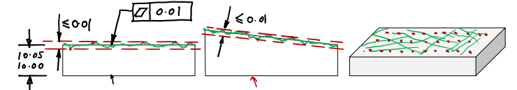
Tolerance zone is defined as the maximum allowable spacing between the closest two planes that enclose all points on the manufactured surface
Tells us nothing about relationship with any other surface
Not used, e.g. , to control thickness uniformity of a plate
Disadvantage of using multiple linear measurements to check flatness is that the relative locations of these measurements are not known, so checking the flatness tolerance against the exact definition described above (maximum distance between two parallel planes) is then not strictly possible
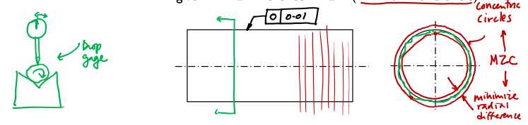
Controls out-of-roundness within any plane perpendicular to the axis of the cylinder
The tolerance value specifies the maximum allowable difference between radii of two concentric circles that are as close together as possible and that enclose all points of the manufactured circumference
Center position of circles is fit to measurement data to give minimal difference in radii (minimum zone circle)
To test this tolerance strictly, one would have to measure the shape of the circumference with stylus, and then use a data-fitting algorithm to identify the two circles with the smallest difference in radii that enclose all points
How far from perfectly circular any particular circumference of a cylindrical feature is allowed to be.
In many machine shops, an approximate measure of circularity is often obtained by placing the component in a
V-block (right), and rotating it while a dial gage stylus rests on the upper surface.
The peak-to-peak, $\Delta d$, deflection of the gage needle is taken as an estimate of out-of-roundness.
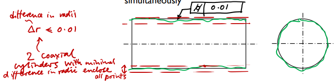
When a circularity tolerance is applied to a cylindrical feature, we require the tolerance to be independently met at all points along its axis.
When we consider all longitudinal positions simultaneously, our tolerance is one of cylindricity:
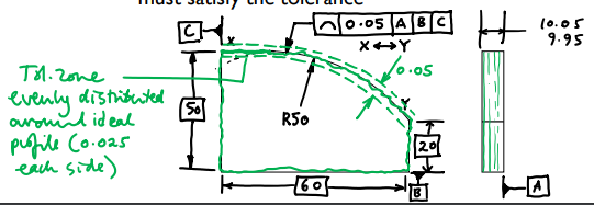
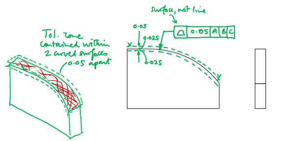
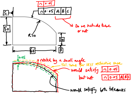
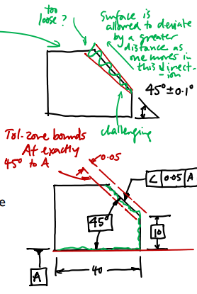
Yellow shows looser tolerance zone without datums; just says that the line’s/surface’s shape has to fit the tolerance – not that that surface itself has to be constrained by it’s to fit with other parts
While form tolerances dictate the required “quality” of a single feature, and profile tolerances may or may not be anchored to a particular datum or datums, orientation tolerances inherently require the use of datums, because they are about relating one feature to another. We need to establish a datum to represent one feature before we can determine how the second feature relates to it. Orientation tolerances are as follows.
One of the features is assigned a datum letter, and the other feature is referenced to it
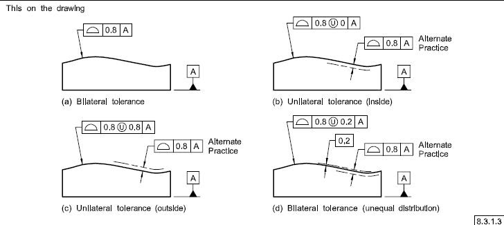
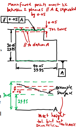
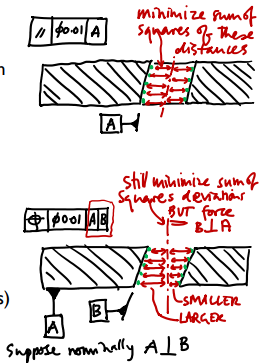
Surface parallelism: when the non-datum feature is a plane, the tolerance zone tells us the maximum allowable distance between two planes which are:
Parallel to the established datum
As close together as possible
Enclose all points on the referenced surface
As with flatness, though, a parallelism tolerance makes no statement about how the distance between the two features should be controlled/where the tolerance zone lies
That distance can be controlled by a separate dimensional tolerance as shown on the left side
E.x Two surfaces could be parallel but the wrong distance apart
Note that a parallelism tolerance is quite different from a flatness tolerance in that the planes being used to check a parallelism tolerance must lie parallel to a specified datum; this requirement does not exist for a flatness tolerance
When the toleranced feature is an axis, we specify a cylindrical tolerance zone with a particular diameter — this tolerance zone is, however, constrained to be parallel to the datum, which differs from a simple straightness tolerance.
If the axis datum is the first datum being established: find best-fit center-line for points measured on the surface of the cylindrical feature (e.g. by CMM)
Best-fit could be found by minimizing, e.g. sum of squared differences from surface points to axis
If other datum(s) have been previously established: the axis datum is also constrained to be perpendicular to previous datum(s)
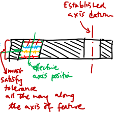
Measure multiple points on the surface of the cylindrical manufactured feature
Find the effective position of the axis at all points along its length
Find “median position” between measured surface points
Manufactured axis will not be perfectly straight
Ask whether all points along the manufactured axis fit within a cylindrical tolerance zone of the specified diameter that has the prescribed relationship to the given datum:
Tolerance zone may be parallel, perpendicular, concentric, etc. relative to datum
Tolerance zone can take the most favorable possible position for meeting the tolerance
Applies along the whole length of the toleranced feature
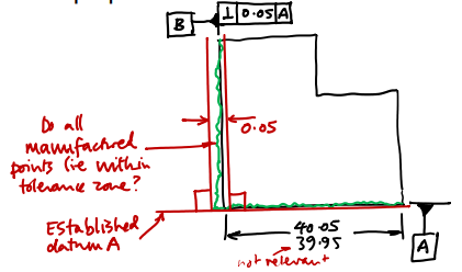
Perpendicularity tolerances are very similar conceptually to parallelism tolerances, but the tolerance feature and datum lie at 90˚ to each other rather than parallel
Can be applied to surfaces and axes
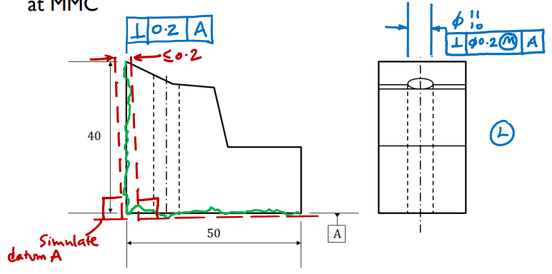
Surface perpendicularity: all points must lie between two planes, separated by the tolerance value and perpendicular to the referenced datum
Axis perpendicularity: all points on the axis must lie within a cylinder with the diameter of the tolerance zone and perpendicular to the referenced datum
Angular tolerance is specified as a number of degrees
Tolerance zone is wedge- shaped
GD&T approach – requires that all points on the tolerance feature lie between two planes that are:
At the specified angle from the given datum, and
Separated by no more than the size of the tolerance zone
An angularity tolerance in GD&T
Note that an angularity tolerance of this kind is rather different from a “traditionally” defined angular tolerance, which would place a range on the effective angle between two features
Note that an angularity tolerance of this kind is rather different from a “traditionally” defined angular tolerance, which would place a range on the effective angle between two features (as shown in the left above). In the traditional approach, the tolerance zone gets wider as the distance from the intersection point between the two features increases. Depending on what the component is supposed to do in use, one might argue that either the traditional approach or the GD&T approach would be the more useful way of tolerancing an angled feature. For example, if the component is intended to serve as a wedge to set the angle between two flat components, the traditional tolerancing approach might work best. On the other hand, if the component is supposed to be a mirror on to which a plane-wave of light is incident, we might rather use the GD&T approach so that the local angle of the surface is kept within certain bounds all the way along its length. The designer needs to think carefully about exactly what manufacturing defect is to be avoided
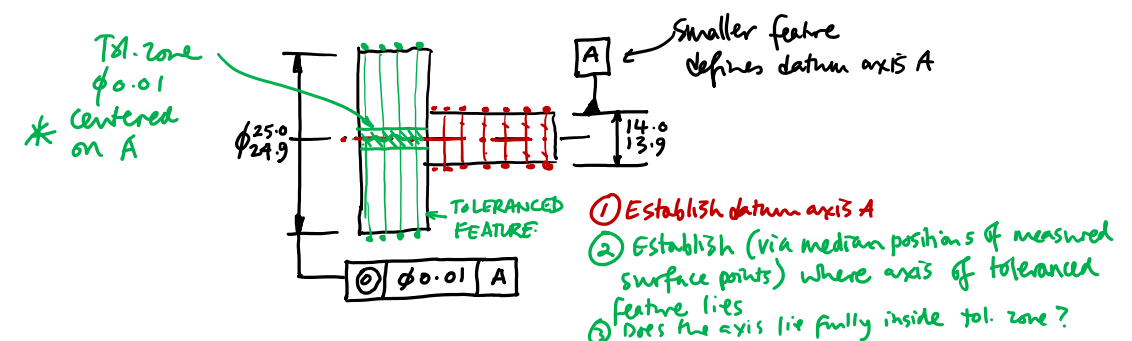
This tolerance is useful, for example, when designing rotating machinery, in which multiple components may need to be placed on a shaft without resulting in out-of-balance loads.
Concentricity relates two axes
One datum axis and one toleranced cylindrical feature
All points on the axis of the tolerance feature must lie within a cylindrical tolerance zone centered on the datum axis
All median points lying mid-way between the two surfaces of the toleranced feature must lie within the tolerance zone
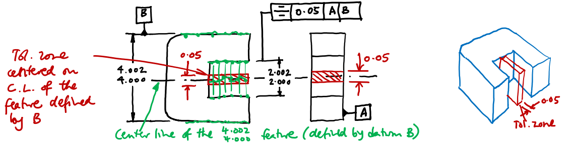
Tolerance zone is centered on the datum feature
Tolerance zone defined by two planes
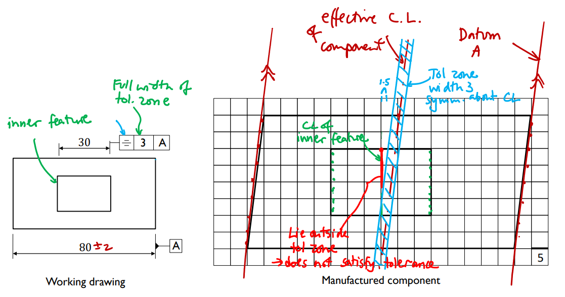
In some components, one feature is intended to be centered relative to another, and a symmetry tolerance defines how far those two features can deviate from symmetry. Here when we say “feature” we refer to opposing pairs of surfaces with equal size — a particular type of feature known as a feature of size. The opposite sides of the slot above constitute a feature of size, as do the opposite outside faces of the component itself. As shown above, one feature is specified as a datum (by labeling one side of the feature with a lettered symbol). The other feature is labeled with its nominal dimension and also with a feature control frame that contains the symmetry symbol, the size of the tolerance zone, and the relevant datum. The tolerance zone tells us how far the midplane of the toleranced feature can deviate relative to the midplane of the datum feature (which would be established by measuring points on both sides of the feature — i.e., the height of the component in the example
Runout tolerances differ from both circularity/cylindricity and concentricity tolerances in that they constrain peak-to-peak deviation of the surface of one feature when it is rotating about a datum axis. (No fitting of bounding circles or cylinders or of effective central axes is required.) Runout tolerances are thus helpful for tolerancing components that must rotate relative to other components while maintaining a certain amount of clearance — for example, a shaft turning within a cylindrical cavity. Runout is also important for ensuring cutting tool performance — in a milling tool or drill for example, limiting runout enables clean cuts to be made, as the tool will not periodically collide with the workpiece.
Runout considers how the surface profile of an object varies as it rotates about a specified axis
Useful for specifying performance of rotating machinery, cutting tools etc.
Circular runout:
Imagine placing a dial gage on the surface of a cylindrical feature
Peak-to-peak variation of the reading as it rotates is circular runout
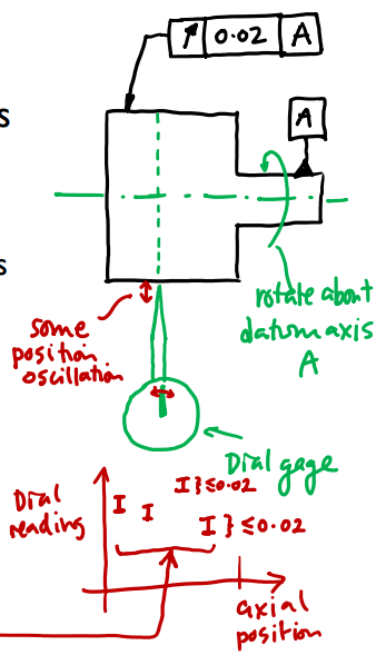
Circular runout tolerance must not be exceeded at any location along the axis of the feature
A circular runout tolerance limits the peak-to-peak deviation of points on any given circumference of a cylindrical feature, when it rotates about the specified datum axis. In the example shown on above, for example, circular runout could be measured by clamping the component in a chuck to establish datum A, then rotating the component with a dial gage in contact with the toleranced feature. The peak-to-peak movement of the indicator would need to be less than the tolerance specified. A circular runout tolerance must be satisfied independently at any circumference on the cylindrical feature to which it applies (not just the location at which the tolerance arrow appears to point).
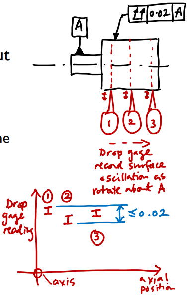
Total runout is more restrictive than circular runout
Imagine taking dial gage readings at many locations along length of feature
Gage readings referenced to the rotation axis (axis = 0)
Peak-to-peak variation of all readings taken together must not exceed tolerance value
This is unlike circular runout, where each axial location is independent
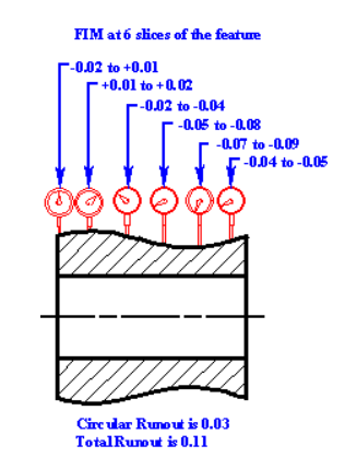
This is the “3D” version of circular runout: the datum is established, and the component rotated, and the total peak-to-peak variation across all axial positions is found (e.g. by scanning a dial gage along the component as it rotates). Total runout will usually be larger than circular runout; the example below illustrates why:
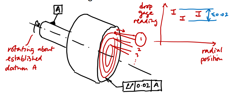
Total runout can be applied to a planar feature perpendicular to the datum axis
Tolerance value must not be exceeded when considering overall peak-to-peak positional variation of all radial locations together
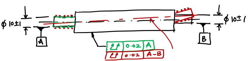
Often, a rotating component will be mounted at two locations (e.g. on two bearings at opposite ends of a shaft). Then, a runout tolerance will be specified relative to both of those datums using the convention illustrated below. The runout using datums A and B in this example is likely to be different from the runout that we would measure using only one of the datums, because the rotational axis established could change position as more points on the component’s surface are included in the fitting process.