Additive manufacturing or “3D printing” has been receiving enormous attention both in industry and as a tool for education and design. Something that sets additive manufacturing apart from other families of processes is the enormous rate of innovation in process technology and machine design, together with the fact that much of this innovation is done by small start-up companies and even by individuals, with the development in some cases being crowd-funded. There are huge differences between the versatility and achievable tolerances of “maker-grade” (or consumer-grade) and industry-grade tools, and in this part of the course we will describe and analyze some of the processes that are available, and provide a framework for analyzing new additive manufacturing tools as they become available.
The richness of innovation in machine design has been helped by the fact that the established players in 2D printing (HP, Epson, etc.) have until very recently been largely absent from 3D printing. This situation has begun to change, especially with the introduction of HP’s “Multi Jet Fusion” systems, but there is no doubt that the market is highly fragmented, and to understand it, one needs knowledge of the underlying material processing principles.
Additive manufacturing has conventionally been seen as a means of prototyping components that would then be mass-produced with some other, faster, process. Prototyping remains an important application, but there are many reasons why one would produce final, functional components additively. Reasons for selecting an additive process over another kind of process include:
Medical implants and prostheses; dental aligners, crowns, bridges, surgical guides, clothing, footwear
Run size too small for custom tooling
There are some components where machining would require too much time and/or labor to be economical, and mass-production techniques such as casting or injection molding would incur considerable tooling costs (complex injection molds can cost tens of thousands of dollars)
The desired geometry cannot be made in any other way
Multi-material, graded stiffness or color
Internal porosity for reduced mass
The idea of “complexity as practical” or that “complexity is free” is often talked about as a distinctive advantage of additive manufacturing.
Reasons for geometrically complex designs: particular aesthetic goals, to improve the aerodynamic performance of a vehicle, or to optimize mechanical properties (e.g. stiffness-to-weight ratio, or compressibility) of a component by introducing fine porous structures that mimic geometries found in nature (e.g. bone, cork, and branched tree-like structures).
Supply chain is challenging in some way (geographically or temporally)
Enables more decentralized/distributed production
Space Station: producing spare parts on the International Space Station — see the start-up company Made in Space that is developing fused deposition modeling tools to work in vacuum and zero-gravity, as well as recycling machines for the printable material, the idea being to produce components on demand without having to wait for a new spacecraft to be launched from Earth to deliver them;
Producing spare parts for military use in theaters of war, where components are frequently needed more quickly than they could be shipped, installing a full machine shop in the field may not be practical, and carrying a comprehensive array of spare parts would be cumbersome
Printing of food, where freshness is important and people decide what they would like to eat just minutes before they eat it.
Assembly costs can be significantly reduced.
Items that would necessitate the use of many components if made with traditional manufacturing approaches could be produced in a single piece by exploiting the extra geometrical flexibility allowed by additive manufacturing, thus saving assembly costs.
Less workers (human controllers) required – cheaper, less (human) error
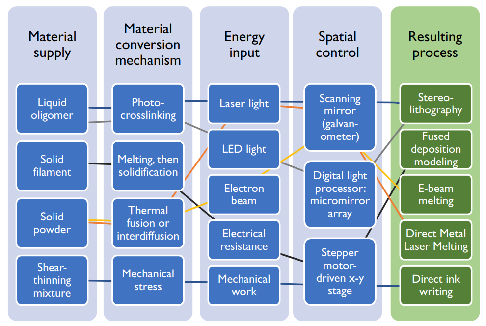
New additive processes and tools enter the market every month, so any detailed description of process technology will rapidly become outdated. Perhaps the most useful way to think about additive manufacturing technology is to isolate the different functions that are involved in any additive process, and consider the multiple independent ways in which each function might be fulfilled. Printing tools could be conceived that combine those solution principles in many different ways:
This is a very rapidly developing field. Some of these seem unrealistic, and they may be, but only for now.Technology is rapidly increasing and what is unfeasible today may be feasible very soon. Think neural networks– we’ve known the underlying concepts since
1873 but only now has technology become fast enough for it to become feasible
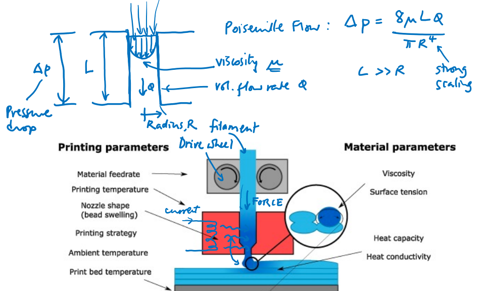
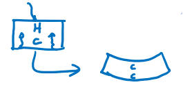
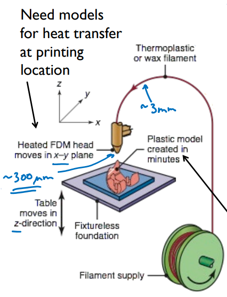
Need models for heat transfer at printing location
Also called Fused Filament Fabrication (FFF)
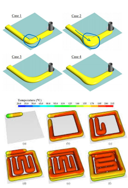
Print time depends strongly on:
Machine,
Component size/geometry,
In-fill strategy
After CAD is complete, model is ran through software (i.e. cura) which turns the model into a series of triangles, which is then used to generate some tool path that forms the model
There’s some information loss throughout this process
Variations at Jacobs
Type A – most basic & common
Single extrusion nozzle (one material)
PLA: Poly Lactic Acid – plant-based, recyclable, but not industrial-grade due to it’s brittleness
Ultimaker 3
PLA, PETG (tougher, bit more flexible than PLA)
Dual nozzle – capable of support material (or just various colors)
LulzbotTaz 6
1.2 mm nozzle
Stratasys Fortus 380 MC
ABS (reasonably tough: lego-brick material); others possible (i.e nylon)
Soluble support
Markforged X7
One of the first printers that enables you to include carbon fiber-reinforced nylon
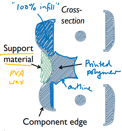
Some FDM machines have two or more extrusion dies which can deposit different materials independently.
One of these extrusion heads might be set up to deposit dedicated support material, which is often soluble in water or a weak NaOH solution and can thus be readily removed from the printed part
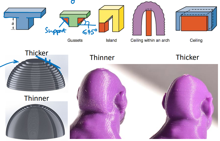
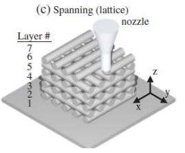
A widely used rule of thumb is that an overhang with an angle of up to 45° can be printed without any support material.
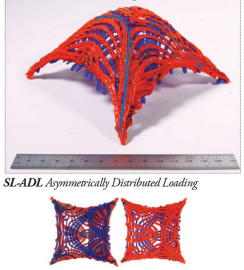
Fused deposition modeling (FDM) [sometimes known as fused filament fabrication (FFF)] is usually carried out layer-by-layer but inter-layer voids or defects can reduce strength or make strength highly directional.
If the filament orientation can be optimized based on knowledge of the way the part will be loaded (i.e. aligning filaments with the principal stress lines), strength could be improved.
This is what SLAM aims to achieve.
Extrusion nozzle path planning is more challenging than in layer-by-layer FDM.
The filament material itself is crucial in determining the performance of the printed object. Filaments with new properties enter the market all the time. Materials with widely varying elasticity are available. It is possible to buy filaments with embedded metal particles, wood particles, carbon powder or even graphene (sheets of few-atom-thick carbon with exceptional in-plane thermal and electrical conductivity). These additives control the optical properties (e.g. reflectivity), and, with a post-printing sintering step, electrical conductivity (enabling printing of e.g. circuit boards) and possibly even thermal conductivity.
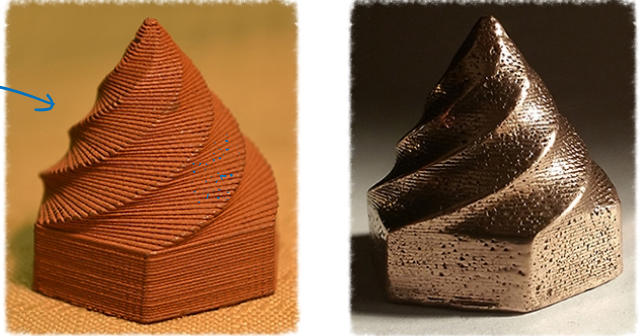
Nevertheless, the working principle of FDM is that a thermoplastic material is temporarily softened inside the print head and then extruded layer by layer on to the emerging component. So it is likely that the largest constituent by volume of any FDM filament will continue to need to be a thermoplastic material. At the moment, organic thermoplastic polymers are the primary ingredient of most filament materials. However, we have already seen the working principle of FDM translated from organic thermoplastic polymers to metals and to glass, which can be extruded in a sufficiently viscous form that it holds its shape long enough to be deposited on to a component.
A heated nozzle brings the feedstock filament close to its melting point, then an electrical current passed through the filament and into the substrate further heats the material causing it to fuse on to the substrate.
It has also been demonstrated with bulk metallic glasses, which are special alloys that remain amorphous at readily attainable cooling rates – i.e. they do not crystallize and can therefore achieve a desirable combination of hardness and toughness.
Meanwhile, use of arc welding in conjunction with robotics to deposit metal has been demonstrated as a lower-resolution, but much faster, way of depositing material
Filament ~85 wt% metal powder; polylactic acid (PLA) binder
Sinter at 980 °C (copper) or 830 °C (bronze) to fuse particles
If you get high enough pressure, then the metal atoms themselves will fuse
You’re not melting the object; shape is retained
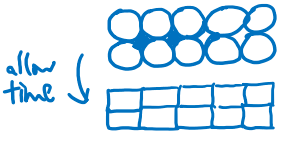
Same side of the coin: pores still exist
“Pores are just cracks waiting to grow” due to their sharp edges
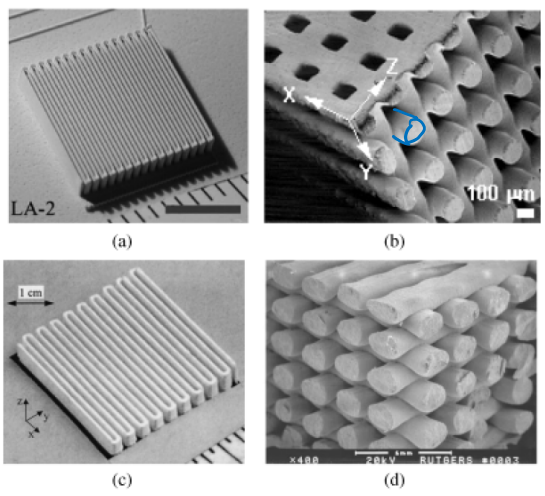
This is a hybrid between FDM and sintering, and involves extruding a paste containing particles of the structural material in a solvent.
The material can be extruded successfully through syringe needles as small as a micrometer in diameter.
Lead zirconium titanate ceramic particles in a solvent dispensed via nozzle
Piezoelectric material
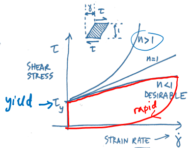
The material paste is
thixotropic, or shear-thinning, which means that when it is loaded and starts to flow, its apparent viscosity falls enabling it to be squeezed through the needle.
Versus than thermally softening polymer (like squeezing toothpaste from a tube)
When its shear strain rate falls again, its viscosity rises, so the extruded structure retains its shape and does not deform significantly under the action of gravity or surface tension.
Once the structure has been printed, heat is applied to drive of the solvent and sinter the particles.
Applications include making micro-scale sensors and actuators, and tissue scaffolds.
Material flow is achieved by using a (shear- thinning) ink
Features down to ~ 1 micrometer possible by extrusion through fine needles
Advantages: heat not required; more material possibilities (notably ceramics)
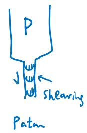
Shear stress in material, .$\tau$, is defined by:
$$\tau = \tau_y + K \dot \gamma ^n$$
.$\tau_y$ is zero-shear-rate yield stress (Pa)
.$K$ is a material constant
.$\hat \gamma$ is shear (deformation) rate (1/s)
.$n$ is shear-thinning exponent (<1 for this process to work)