03-01: Voltage Dividers #
Voltage Divider #
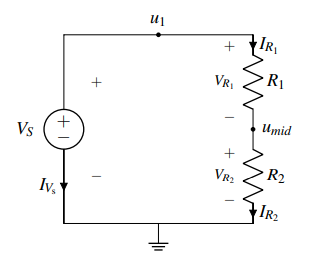
- The voltage divider circuit consists of a voltage source (.$V_S$) and two resistors (.$R_1$ and .$R_2$)
- Example:4. Find expressions for element currents for all elements (except the voltage source) – all steps on page 3
- We label the node connected to the voltage supply as .$u_1 (= V_S)$, since the voltage supply goes between this node and ground.
- Label the remaining node as .$u_\text{mid}$ and the voltages and currents through every element in the circuit with .$V_i$ and .$I_i$ respectively
- Write KCL equations for all nodes with unknown voltage - in this case, this is just .$u_\text{mid}$, since .$u_1 = V_S$.
- The current entering that node is .$I_{R_1}$ and the current leaving it is .$I_{R_2}$
- Since these currents must be equal, .$I_{R_1} = I_{R_2}$
 5. Substitute the element currents into our KCL equation. We have $$I_{R_1} = I_{R_2} \Longrightarrow \frac{V_S - u_\text{mid}}{R_1} = \frac{u_\text{mid}}{R_2}$$ 7. Solve the above equation. Rearranging, we find that $$V_S R_2 −u_\text{mid}R_2 = u_\text{mid}R_1$$ $$ \Longrightarrow u_\text{mid}(R_1 +R_2) = V_SR_2$$ $$ \Longrightarrow u_\text{mid} = \frac{R_2}{R_1 + R_2} V_S = \frac{1}{1+ \frac{R_1}{R_2}} V_S = \alpha V_S$$
$$I_{R_1} = \frac{V_S - u_\text{mid}}{R_1}$$
$$I_{R_2} = \frac{u_\text{mid}}{R_2}$$
The reason this circuit is called a “voltage divider” is that we can create any output voltage of .$u_\text{mid} = \alpha V_S$ for any .$\alpha \in [0,1]$ (assuming that all of the resistance values are non-negative) by varying the ratio of the resistor values .$R_1/R_2$. As we will see shortly, varying this ratio is exactly the mechanism we will use to convert the relative position of a user’s touch to a voltage.
.$R_2$, the resistor in the numerator, is the one next to ground. .$R_1$ is connected to a non-zero voltage node (in this case .$u_1 = V_S$).
Capacitor Divider #
The capacitor divider is similar, differing in that the numerator is now the component closest to $V_{in}$ rather than closest to ground (as in the voltage divider with resistors) $$V_{out} = \frac{C_1}{C_1 + C_2} V_{in}$$

Current Divider #
Current $I_X$ in a resistor $R_X$ that is in parallel with a combination of other resistors of total resistance $R_T$ is $$I_X = \frac{R_T}{R_X + R_T}I_T$$
- $I_T$ is the total current entering the combined network of $R_X$ in parallel with $R_T$
- $R_T$: Total resistance of the circuit to the right of resistor $R_X$

03-03: Power and Voltage/Current Measurement #
Physics of Circuits #
- Power refers to the rate of energy change, .$P = \frac{dE}{dt} \text{ [Watts]}$
- .$\dots \Longrightarrow dE = V\ dQ \Longrightarrow \frac{dE}{dt} \equiv P = V \frac{dQ}{dt} = VI$
- .$P_\text{el} = I_\text{el} \cdot V_\text{el} = V^2_\text{el} \cdot R^{-1}_\text{el} = I^2 _\text{el} R _\text{el}$
- $P > 0 \implies$ (positive) power dissipated, negative power generated.
- By PSC, resistors always dissipate power because current enters the .$+$ terminal
- Voltage sources tend to generate power, since current comes out of the .$+$ terminal (and the product .$P = IV < 0$)
- $P < 0 \implies$ (positive) power generated, negative power dissipated.
- In an
isolated (circuit) system, the sum of the power (across all components) should equal zero by conservation of energy
- Useful sanity-check
- .$\dots \Longrightarrow dE = V\ dQ \Longrightarrow \frac{dE}{dt} \equiv P = V \frac{dQ}{dt} = VI$
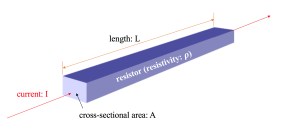
- .$R = \rho \frac{L}{A}$
Touchscreen #
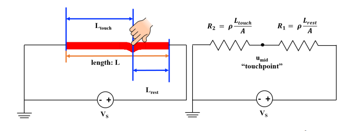
- Given that the top (red) layer has a resistivity .$\rho$ and a cross-sectional area .$A$, the resistance of the top layer from the touchpoint to the right-hand end is given by .$R_1 = \rho \frac{L_\text{rest}}{A}$, the resistance of the top layer from the left-hand end to the touchpoint is given by .$R_2 = \rho \frac{L_\text{touch}}{A}$
- We can see that .$u_\text{mid}$ can be found because it’s a voltage divider:
$$u_\text{mid} = \frac{\rho \frac{L_\text{touch}}{A}}{\rho \frac{L_\text{rest}}{A} + \rho \frac{L_\text{touch}}{A}}V_S = \frac{L_\text{touch}}{L_\text{touch} + L_\text{rest}}V_S = \frac{L_\text{touch}}{L}V_S$$
- .$L = L_\text{touch} + L_\text{rest}$: The length of the touchable portion of the screen
The relationship we have found between .$u_\text{mid}$ and .$V_S$ is very convenient because .$u_\text{mid}$ is not dependent on any material property such as .$\rho$ and .$A$. This means that the top layer can be built with any material and the relationship between .$u_\text{mid}$ and .$V_S$ is still valid. There are always some non-idealities in the world – by making .$u_\text{mid}$ independent of any material property, we can make the circuit model immune to such non-idealities. We also have the freedom to choose a material for the top layer that is good for display purposes (rather than needing a specific material for the touchscreen to work).
Measuring a Circuit #
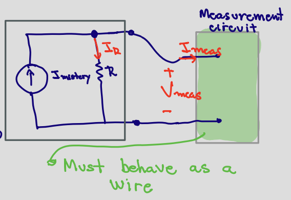
The voltmeter measures voltage across the circuit, while the ammeter needs to be put in-line with the circuit so that the current flows through the ammeter.
- The measurement should not change the energy of the circuit
- It turns out that the most complete and concise way of guaranteeing these measurement tools do not influence the circuit is to state that they do not allow any power dissipated through the measurement device.
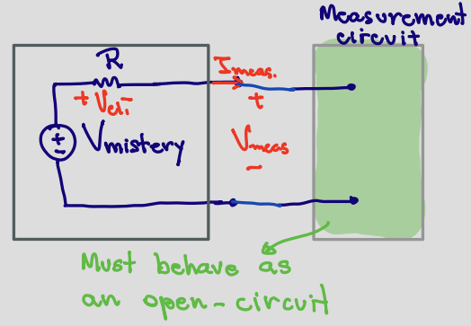
Voltmeter #
Because our voltmeter is made to measure voltage, we can naturally assume that the .$V \neq 0$; this means that a voltmeter must have .$I = 0$ going into it to ensure .$P = IV = 0$.
.$I=0$ occurs when in open-circuits, where exactly zero current is flowing.
Recall that, for a given voltage, the higher the associated resistance, the lower the current and therefore the lower the dissipated power. That is, .$\lim{R \to \infty} \Longrightarrow I = 0$
$$V_\text{el1} = I_\text{meas} R$$ $$V_? - V_\text{el1} - V_\text{meas} = 0$$ $$\Longrightarrow V_? = V_\text{el1} + V_\text{meas}$$ $$\Longrightarrow V_? = I_\text{meas} R + V_\text{meas}$$ $$\therefore V_? = V_\text{meas} \iff I_\text{meas} = 0$$
$$I_\text{meas} = \frac{V_\text{meas}}{R_\text{meas}}$$ $$\therefore I_\text{meas} = 0 \iff R_\text{meas} \gg V_\text{meas}$$
Voltmeters are added in parallel to the circuit, otherwise they would stop the current from flowing.
Ammeter #
The ammeter has the circuit’s current flowing through it. Therefore, to ensure .$P = IV = 0$, the ammeter needs .$V = 0$.
.$V=0$ occurs in short-circuits (ideal wires), where exactly zero potential difference exists
$$I_? = I_R + I_\text{meas}$$ $$\therefore I_? = I_\text{meas} \iff I_R = 0$$
$$I_R = \frac{V_\text{meas}}{R}$$ $$\therefore I_R = 0 \iff V_\text{meas} = 0$$
Ammeters are added in series to the circuit, otherwise they would short-circuit the measured component.